Introduction
簡介
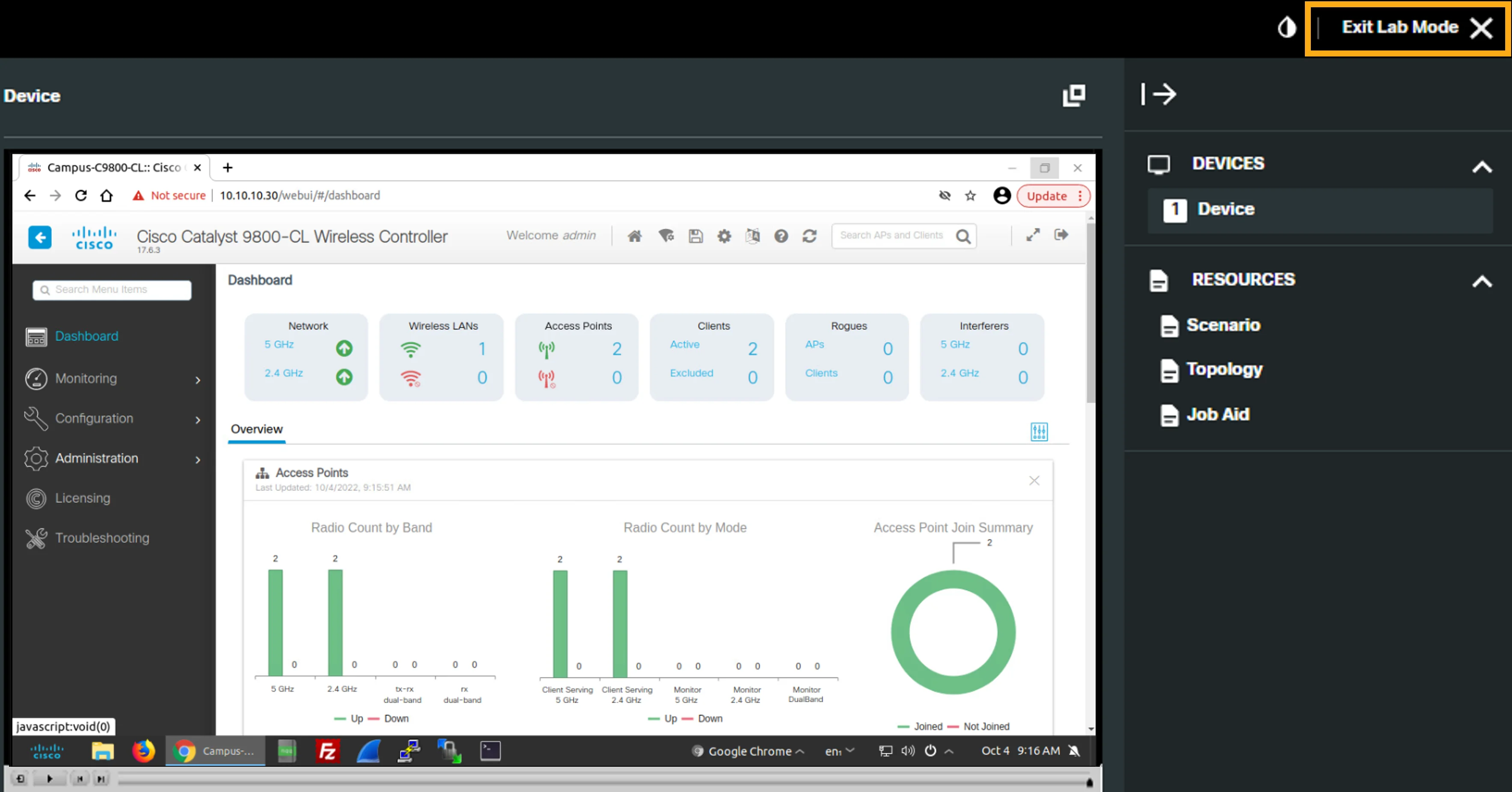
After completing this activity, you will know how to configure an open wireless network on a Cisco Catalyst 9800 WLC and how to verify the wireless network connection.
完成本活動後,你將知道如何在 Cisco Catalyst 9800 WLC 上設定開放式無線網路,以及如何驗證無線網路連線。
Topology
拓樸
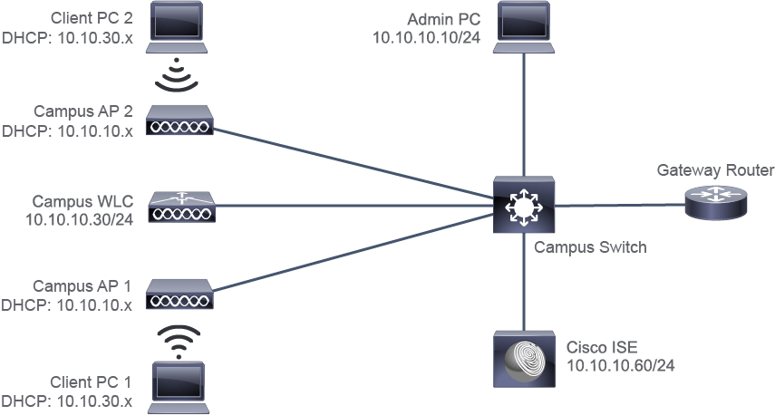
Job Aid
工作輔助資料
Device Information
裝置資訊
Device 裝置 | Username/Password 使用者名稱/密碼 | Management IP Address 管理 IP 位址 | Employee Network (VLAN 30, WLAN employee) IP Addresses 員工網路(VLAN 30,WLAN employee)IP 位址 |
Admin PC 管理用 PC | 10.10.10.10/24 10.10.10.10/24 | ||
Client PC 1 用戶端 PC 1 | DHCP: 10.10.30.x/24 DHCP:10.10.30.x/24 | ||
Client PC 2 用戶端 PC 2 | DHCP: 10.10.30.x/24 DHCP:10.10.30.x/24 | ||
Campus WLC Campus WLC | admin/1234QWer admin/1234QWer | 10.10.10.30/24 10.10.10.30/24 | 10.10.30.30/24 10.10.30.30/24 |
Campus AP 1 Campus AP 1 | DHCP: 10.10.10.x/24 DHCP:10.10.10.x/24 | ||
Campus AP 2 Campus AP 2 | DHCP: 10.10.10.x/24 DHCP:10.10.10.x/24 | ||
Cisco ISE Cisco ISE | 10.10.10.60/24 10.10.10.60/24 | ||
Gateway Router 閘道路由器 | 10.10.10.1/24 10.10.10.1/24 | 10.10.30.1/24 10.10.30.1/24 |
Task 1: Configure an Open Wireless Network
任務 1:設定開放式無線網路
Wireless network services are a fundamental part of modern networks.
無線網路服務是現代網路的基本組成部分。
You will configure a Cisco Catalyst 9800 WLC to provide users with access to the enterprise network over an open wireless network.
你將設定 Cisco Catalyst 9800 WLC,讓使用者能透過開放式無線網路存取企業網路。
Cisco Catalyst 9800 WLC Configuration Overview
Cisco Catalyst 9800 WLC 設定總覽
Cisco Catalyst 9800 WLCs are based on Cisco IOS XE, and use a configuration data model that is based on design principles of reusability, simplified provisioning, enhanced flexibility, and modularization to help manage networks as they scale and simplify management of dynamically changing business and IT requirements.
Cisco Catalyst 9800 WLC 是以 Cisco IOS XE 為基礎,並採用一套設定資料模型,該模型以可重複使用性、簡化布建、增強彈性與模組化為設計原則,有助於在網路規模擴大時進行管理,並簡化動態變化的商業與 IT 需求管理。
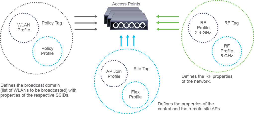
Elements of the Cisco Catalyst 9800 WLC Configuration Model
Cisco Catalyst 9800 WLC 設定模型的組成元素
The following are the elements of the Cisco Catalyst 9800 WLC configuration model:
以下是 Cisco Catalyst 9800 WLC 設定模型的組成元素:
- Tags:A tag is defined by the property of the policies that are associated with it, which in turn is inherited by an associated client or an AP. There are various types of tags, each of which is associated with different profiles. Every tag has a default that is created when the system boots up.標籤(Tag):標籤是由與其相關聯的原則(policy)屬性所定義,這些屬性再由相關聯的用戶端或 AP 所繼承。標籤有多種類型,每一種都與不同的設定檔(profile)相關聯。每個標籤在系統開機時都會建立一個預設值。
- Profiles:A profile is a set of attributes that are applied to the clients that are associated with the APs or the APs themselves. There are different kinds of profiles depending on the characteristic of the network that they define. These profiles are in turn part of a larger construct that is called a tag. Profiles are reusable entities and can be used across tags.設定檔(Profile):設定檔是一組套用到與 AP 相關聯的用戶端,或套用到 AP 本身的屬性。依網路所定義特性的不同,設定檔也有不同種類。這些設定檔又是稱為標籤(tag)的更大架構的一部分。設定檔可重複使用,並能跨標籤使用。
Association of Tags with APs
將標籤與 AP 建立關聯
An AP is tagged based on a broadcast domain, the site it belongs to, and the RF characteristics desired. Once tagged, the AP gets a list of WLANs to be broadcast along with the properties of the respective SSIDs, properties of the APs on the local/remote site, and the RF properties of the network. By default, an AP is tagged with the default policy, site, and RF tag unless explicitly changed. When a tag that is associated with an AP is changed, the AP resets its CAPWAP connection.
AP 會依據廣播網域、所屬站點以及所需的射頻(RF)特性來加上標籤。加上標籤後,AP 會取得要廣播的 WLAN 清單,以及對應 SSID 的屬性、本地/遠端站點上 AP 的屬性,以及網路的射頻屬性。根據預設,除非明確變更,否則 AP 會使用預設的原則、站點與射頻標籤。當與 AP 相關聯的標籤變更時,該 AP 會重設其 CAPWAP 連線。
Wireless Setup Wizards
無線設定精靈
The Cisco Catalyst 9800 WLC wireless setup wizards (Basic and Advanced) use intent-based workflows to guide you through the configuration process to define local and remote sites, create wireless networks for these sites, define policies such as VLAN, ACL, and QoS policies, and fine-tune RF characteristics. Corresponding policies and tags are created in the back end in accordance with the new configuration model and are transparent to the user. APs are assigned to the site and in turn are assigned policy, RF, and site tags.
Cisco Catalyst 9800 WLC 的無線設定精靈(基本與進階)採用以意圖為導向的工作流程,引導你完成設定程序,定義本地與遠端站點、為這些站點建立無線網路、定義 VLAN、ACL 與 QoS 等原則,並微調射頻特性。相對應的原則與標籤會在後端依照新的設定模型自動建立,對使用者而言是透明的。AP 會被指派到站點,並依次被指派原則、射頻與站點標籤。
Cisco Catalyst 9800 WLC Configuration
Cisco Catalyst 9800 WLC 設定
In the following steps, you will use the basic wireless setup configuration feature to add a location, add a WLAN, configure WLAN security settings, map the WLAN to a VLAN, and add APs to the location. The basic wireless setup configuration feature will automatically create and configure the required configuration elements, such as tags and profiles to apply the settings that you explicitly configured and the default values that you left unchanged.
在接下來的步驟中,你將使用基本無線設定功能來新增位置、新增 WLAN、設定 WLAN 安全性設定、將 WLAN 對應到 VLAN,並將 AP 新增到該位置。基本無線設定功能會自動建立並設定所需的設定元素,例如標籤與設定檔,以套用你明確設定的值以及你未變更的預設值。
Activity
活動
Add a New Location
新增位置
A location is an entity that groups WLANs, and the associated APs of a certain area that the WLC controls.
位置(location)是將某個區域的 WLAN 及其相關聯的 AP 分組的實體,由 WLC 管理。
Click the Play icon in the middle of the screen or the Play button on the player below the simulation screen to begin the simulation.
按一下畫面中央的 Play 圖示,或按一下模擬畫面下方播放器上的 Play 按鈕,開始進行模擬。
On the Admin PC, in the Campus WLC web GUI, choose Configuration > Wireless Setup > Basic.
在管理用 PC 上的 Campus WLC 網頁 GUI 中,選擇 Configuration > Wireless Setup > Basic。
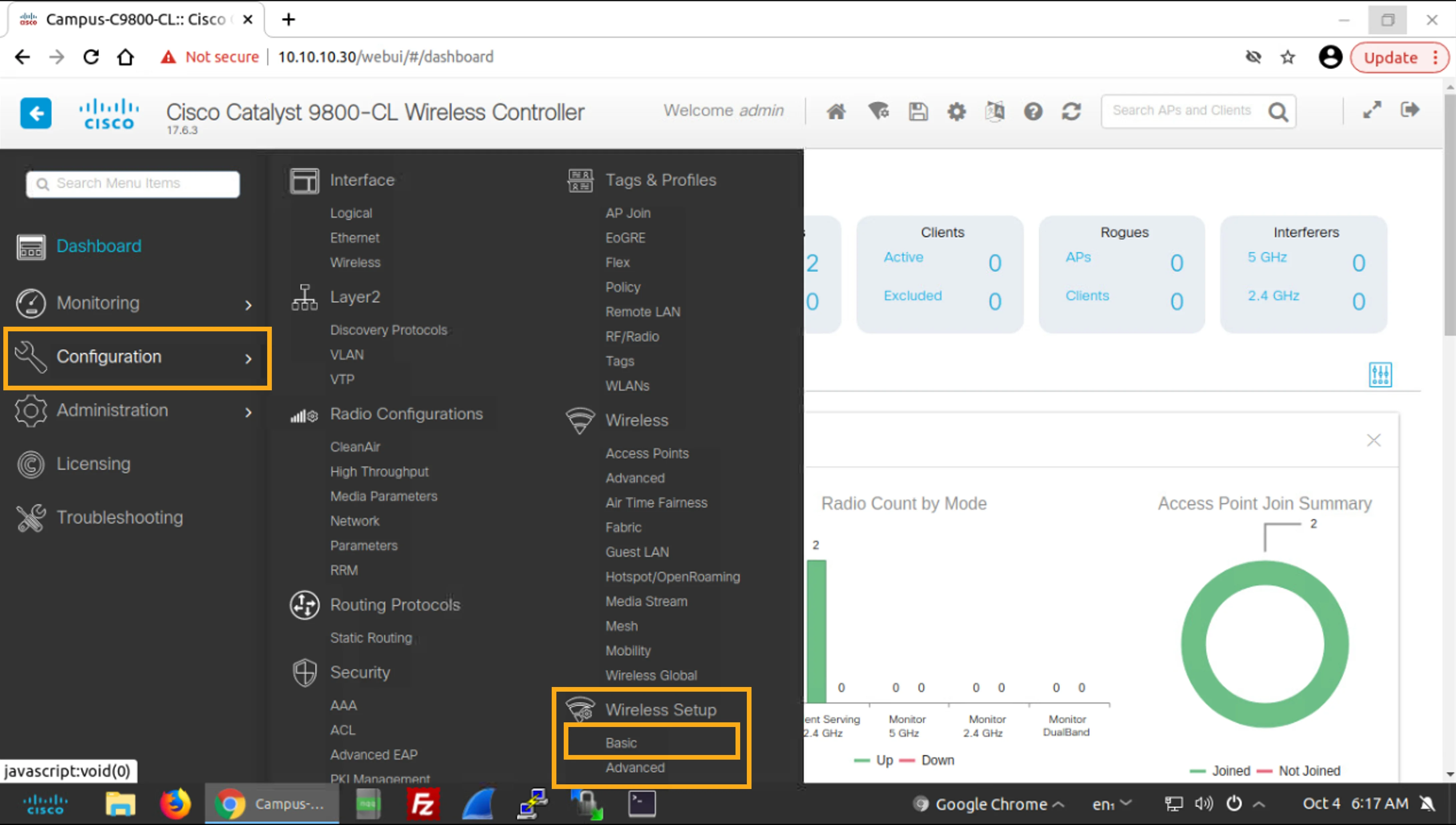
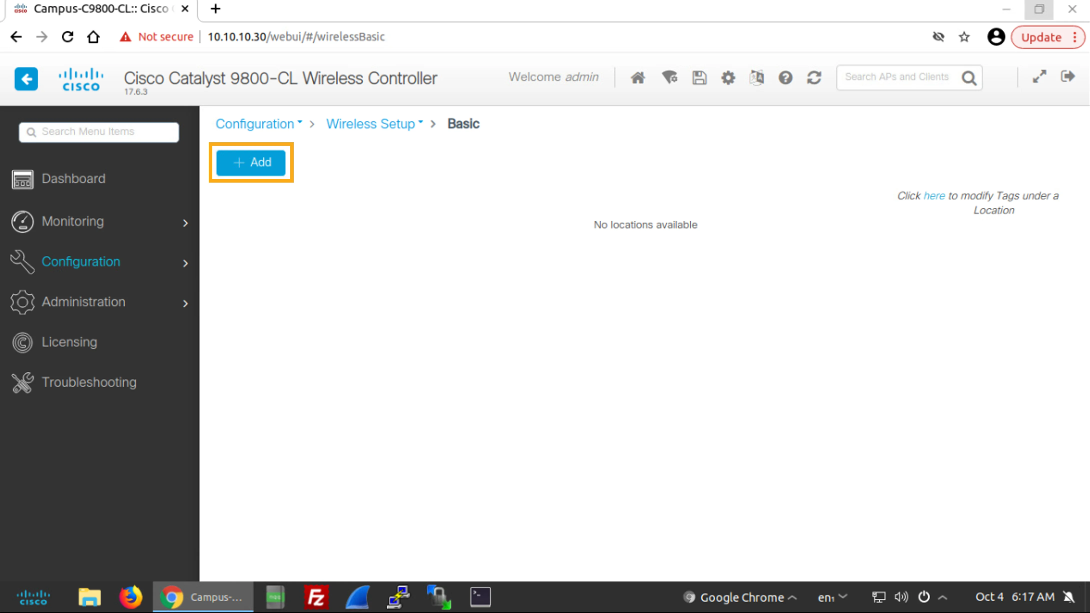
Click the +Add button to add a new location and configure the following general location settings:
按一下 +Add 按鈕以新增位置,並設定下列一般位置設定:
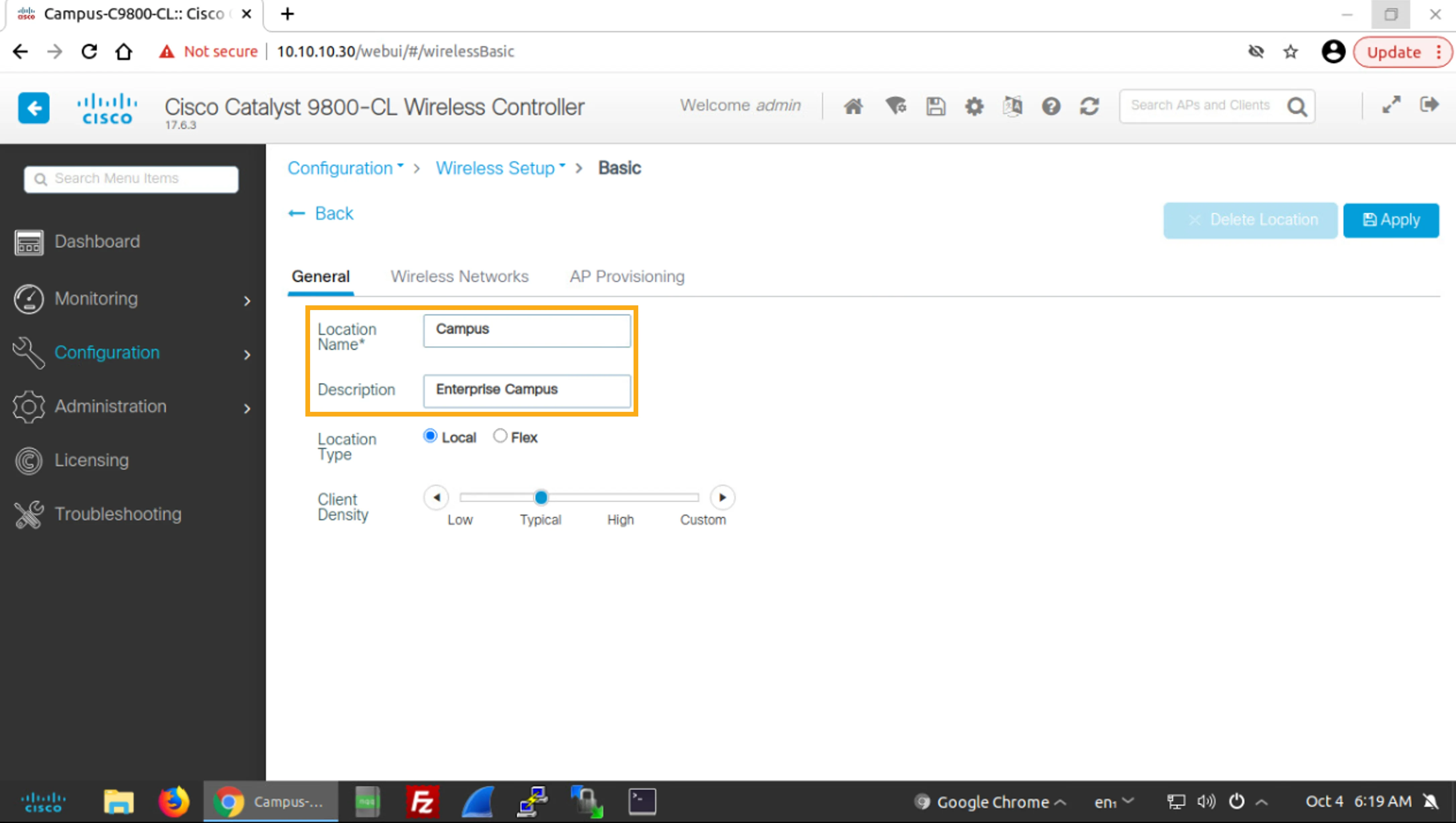
Location Name Location Name | Campus Campus |
Description Description | Enterprise Campus Enterprise Campus |
In particular, perform the following procedure to configure location information:
請依照下列程序來設定位置資訊:
- Click +Add.按一下 +Add。
- You are now on the General tab. Click in the Location Name input field and enter Campus.現在你位於 General 標籤頁。按一下 Location Name 輸入欄位並輸入 Campus。
- Then, click in the Description input field and enter Enterprise Campus.接著,按一下 Description 輸入欄位並輸入 Enterprise Campus。
Add a WLAN to the Location
為位置新增 WLAN
Now you will populate the location with a WLAN.
現在你將為該位置填入一個 WLAN。
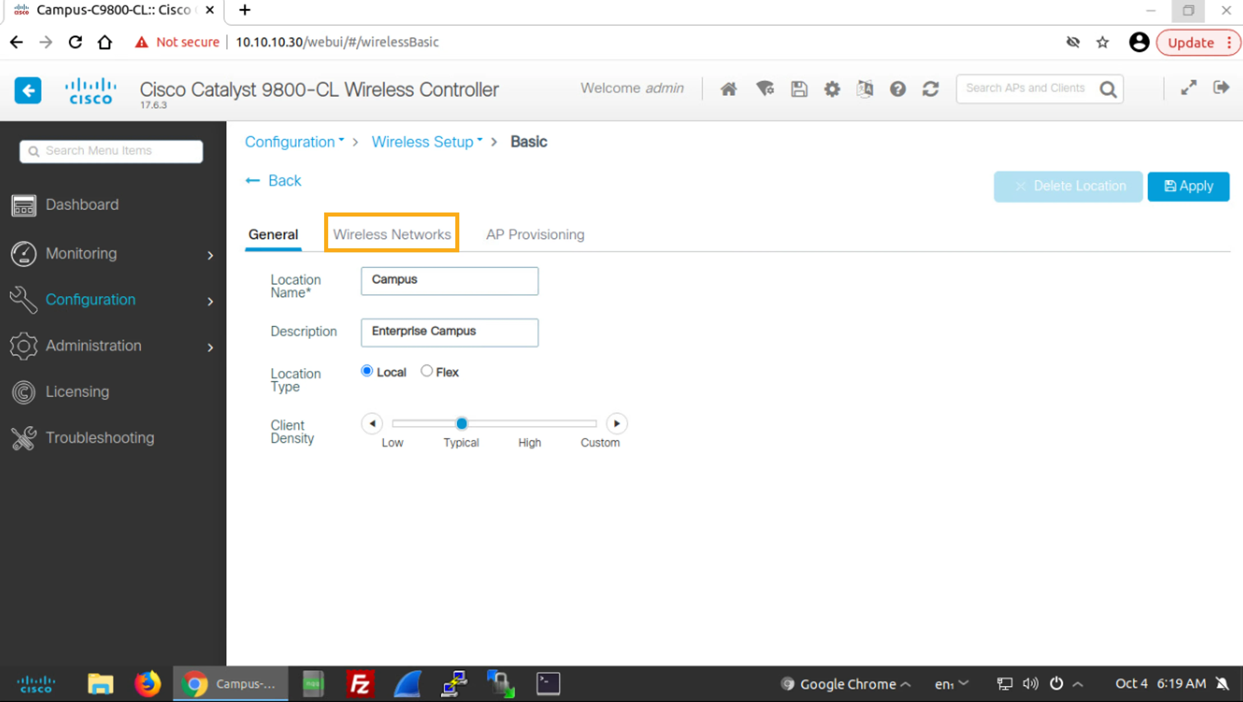
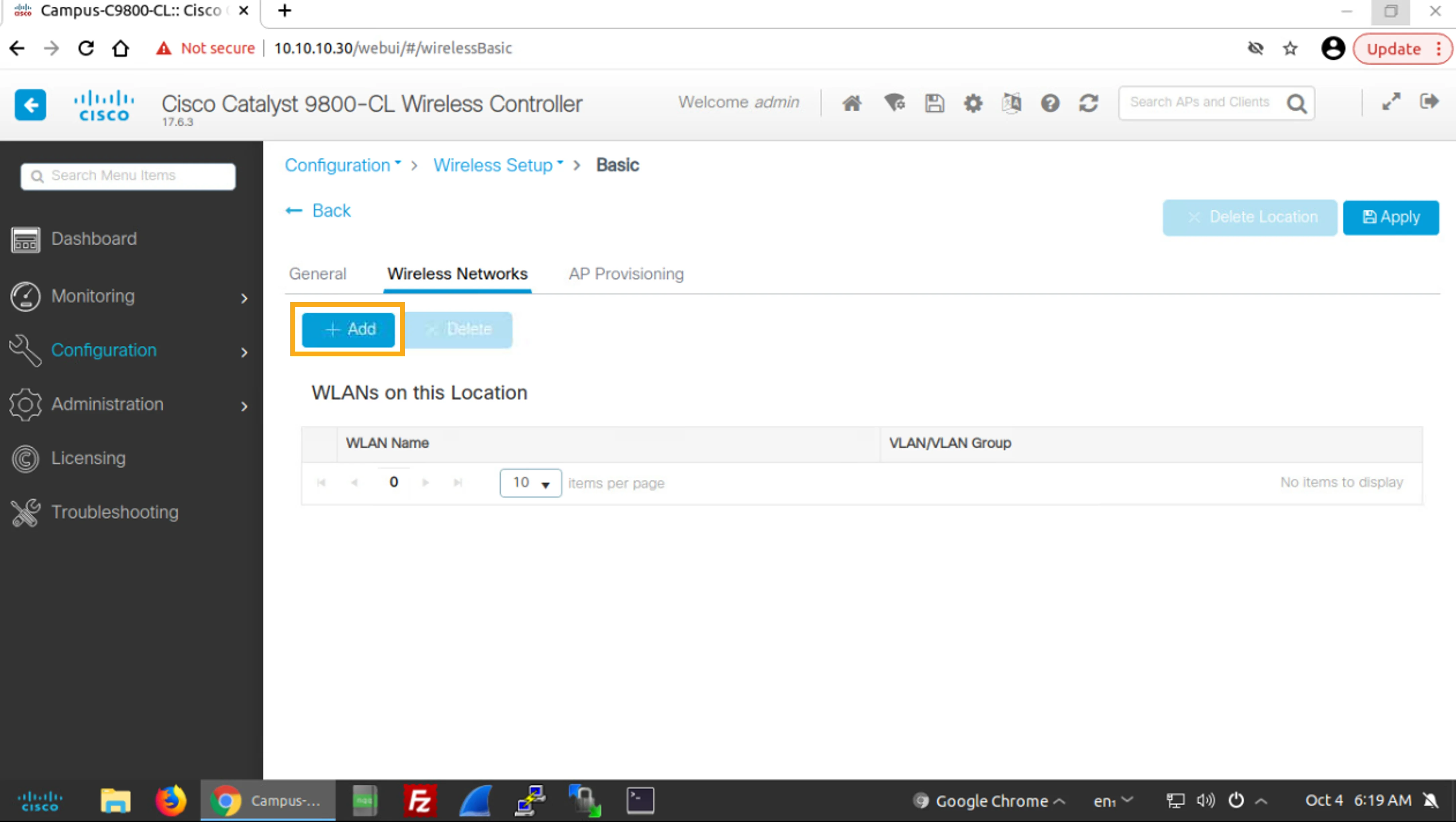
Click the Wireless Networks tab and then click the +Add button to add a new WLAN to the location.
按一下 Wireless Networks 標籤頁,然後按一下 +Add 按鈕,為該位置新增一個 WLAN。
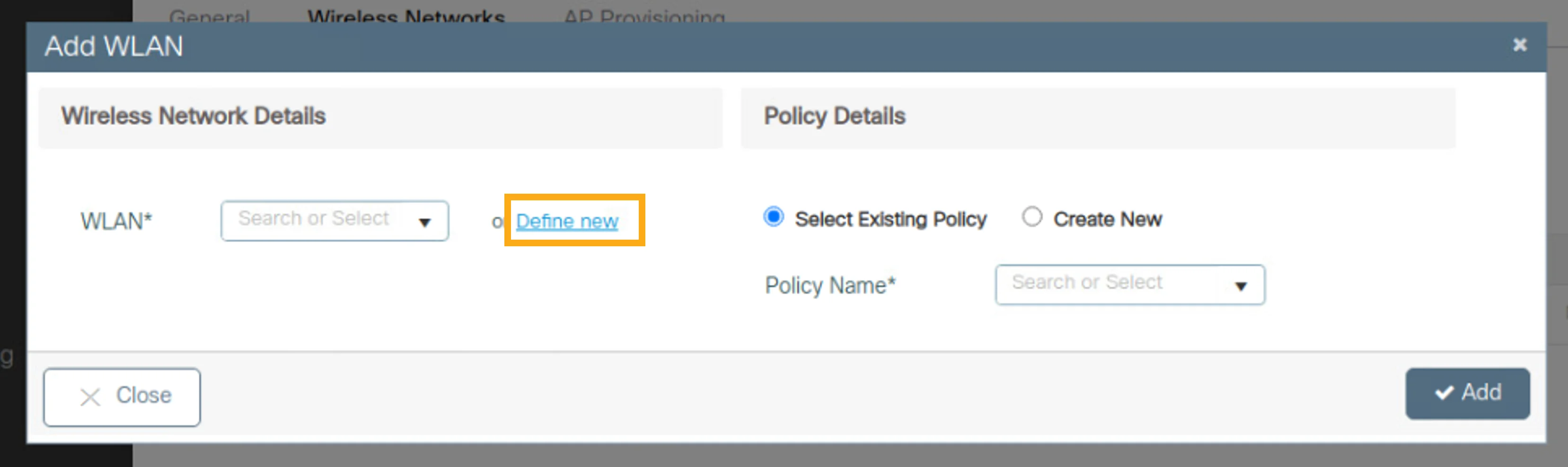
In the Add WLAN window, under Wireless Network Details, click Define new.
在 Add WLAN 視窗中,於 Wireless Network Details 下,按一下 Define new。
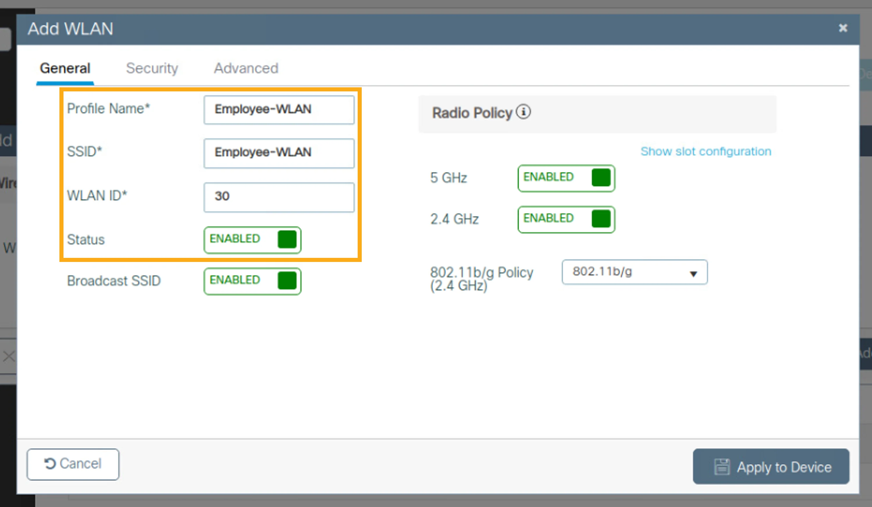
Configure the WLAN with the following settings:
使用下列設定來設定 WLAN:
Profile Name Profile Name | Employee-WLAN Employee-WLAN |
SSID SSID | Employee-WLAN Employee-WLAN |
WLAN ID WLAN ID | 30 30 |
Status Status | ENABLED ENABLED |
In particular, perform the following procedure to configure the WLAN:
請依照下列程序來設定此 WLAN:
- In the General tab, click in the Profile Name input field and enter Employee-WLAN.在 General 標籤頁中,按一下 Profile Name 輸入欄位並輸入 Employee-WLAN。
- Click in the SSID input field and enter Employee-WLAN.按一下 SSID 輸入欄位並輸入 Employee-WLAN。
- Click in the WLAN ID input field and enter 30.按一下 WLAN ID 輸入欄位並輸入 30。
- Click in the Status slider that currently shows DISABLED to change it to ENABLED.按一下目前顯示 DISABLED 的 Status 滑動開關,將其變更為 ENABLED。
The configuration should look like this:
設定畫面應如下所示:
Configure the Layer 2 WLAN Security
設定第 2 層 WLAN 安全性
You will want to configure some basic security in a newly created WLAN.
你會想在新建立的 WLAN 中設定一些基本安全性。
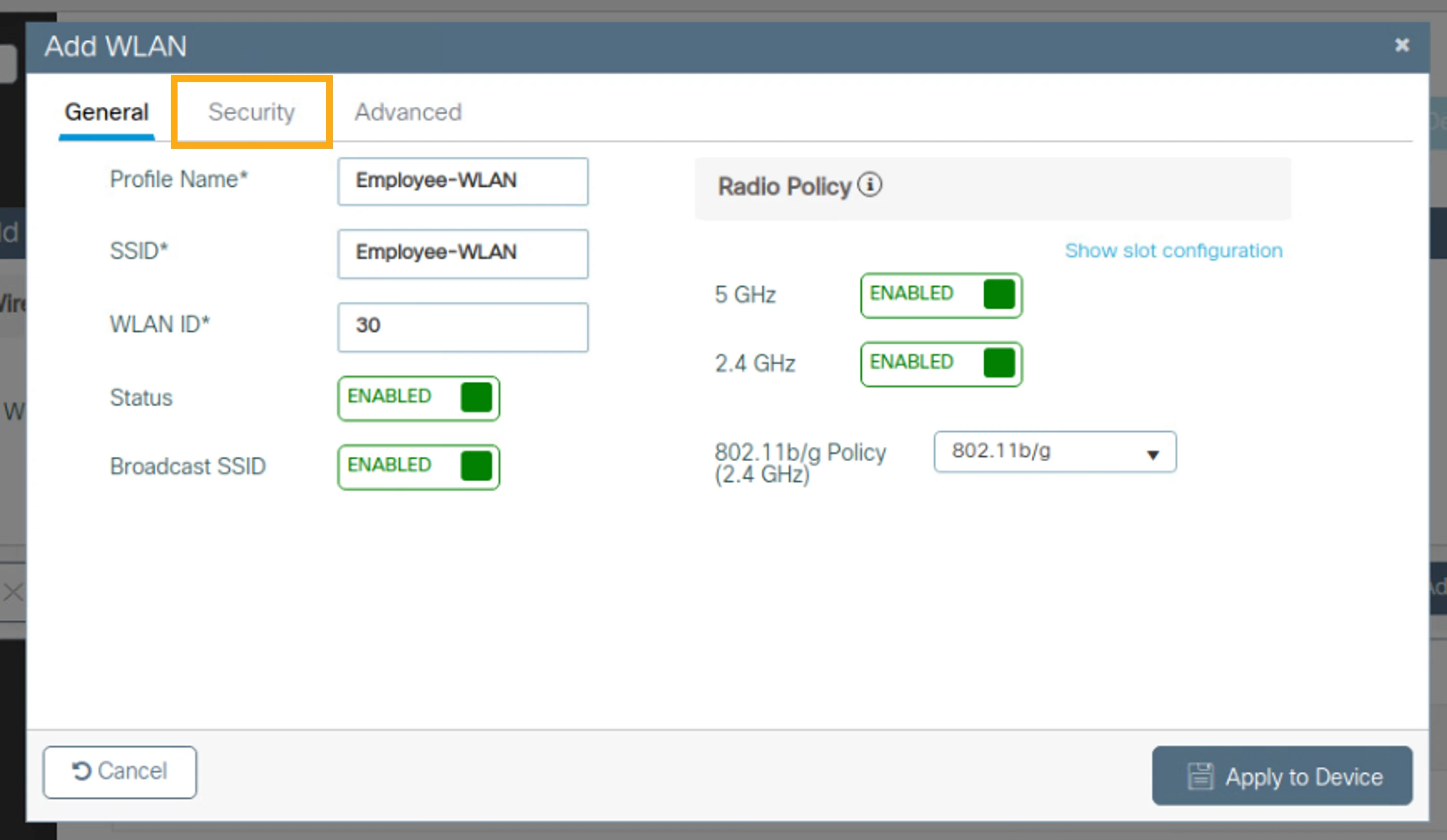
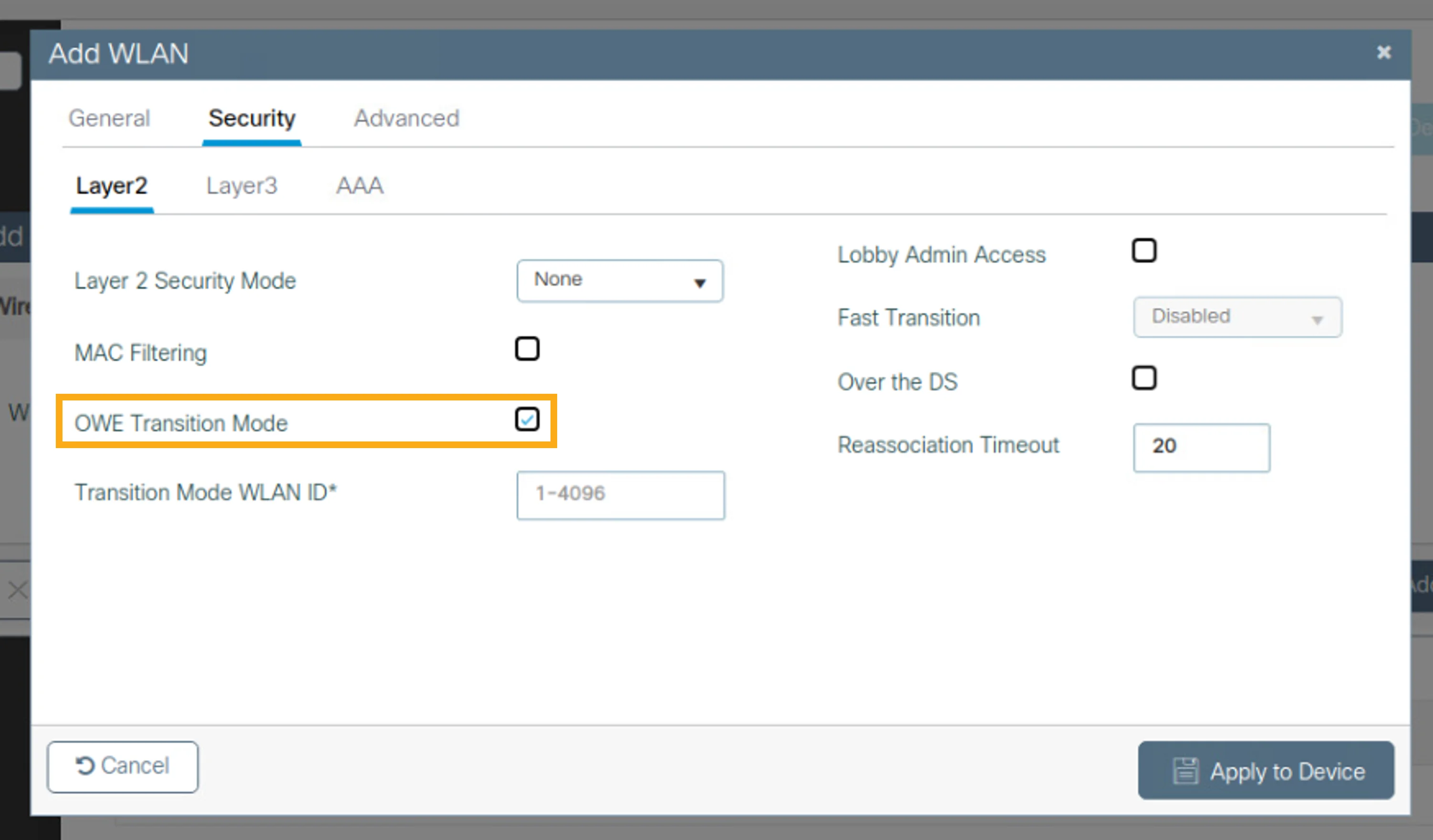
Click the Security tab and configure the following Layer 2 WLAN security settings:
按一下 Security 標籤頁,並設定下列第 2 層 WLAN 安全性設定:
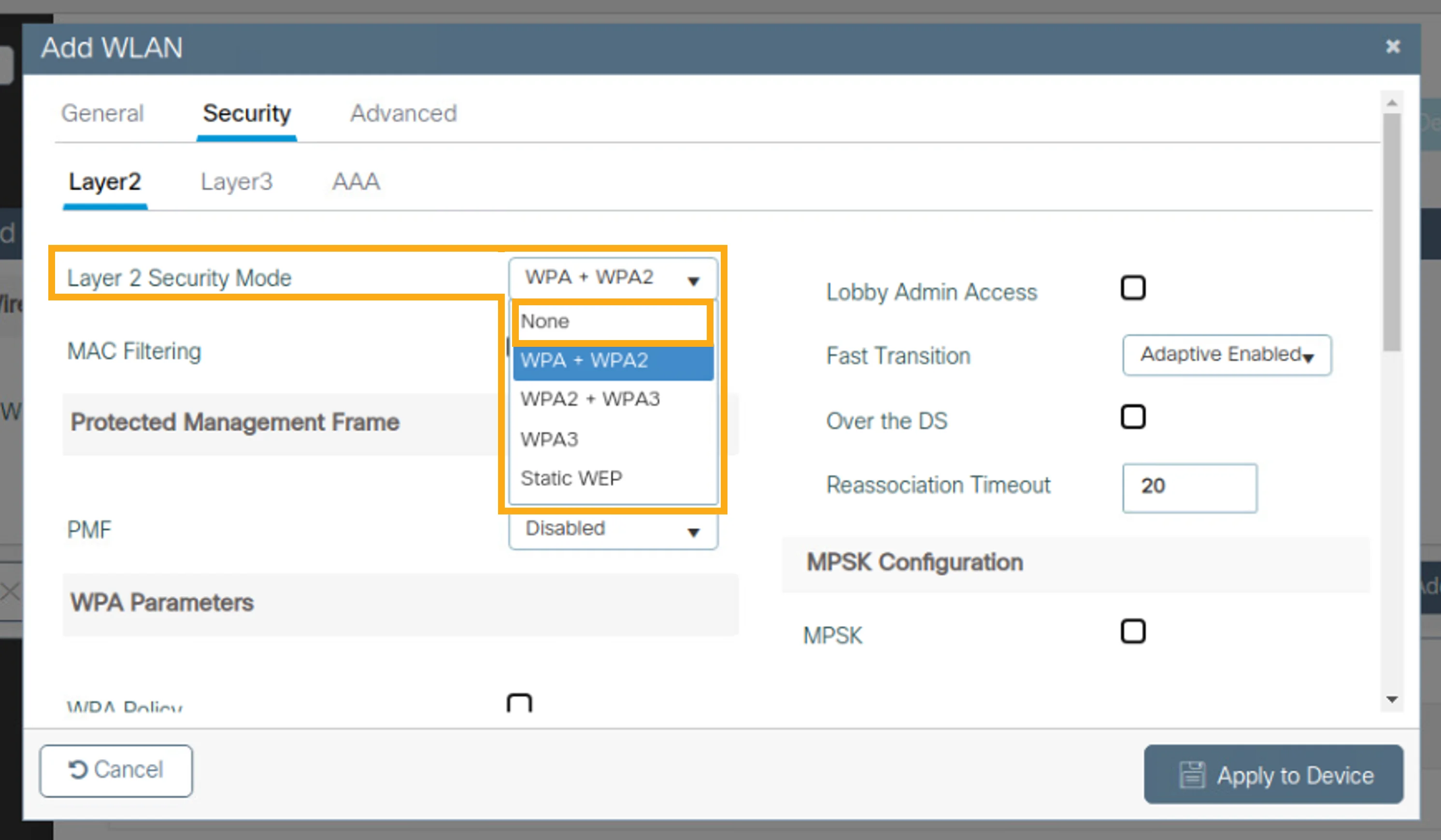
Layer 2 Security Mode Layer 2 Security Mode | None None |
OWE Transition Mode OWE Transition Mode | unchecked unchecked |
In particular, perform the following procedure to configure Layer 2 security:
請依照下列程序來設定第 2 層安全性:
- Click the Security tab.按一下 Security 標籤頁。
- In the Layer 2 Security Mode drop-down list, choose None.在 Layer 2 Security Mode 下拉式清單中,選擇 None。
- Click the OWE Transition Mode check box to disable OWE mode.按一下 OWE Transition Mode 核取方塊以停用 OWE 模式。
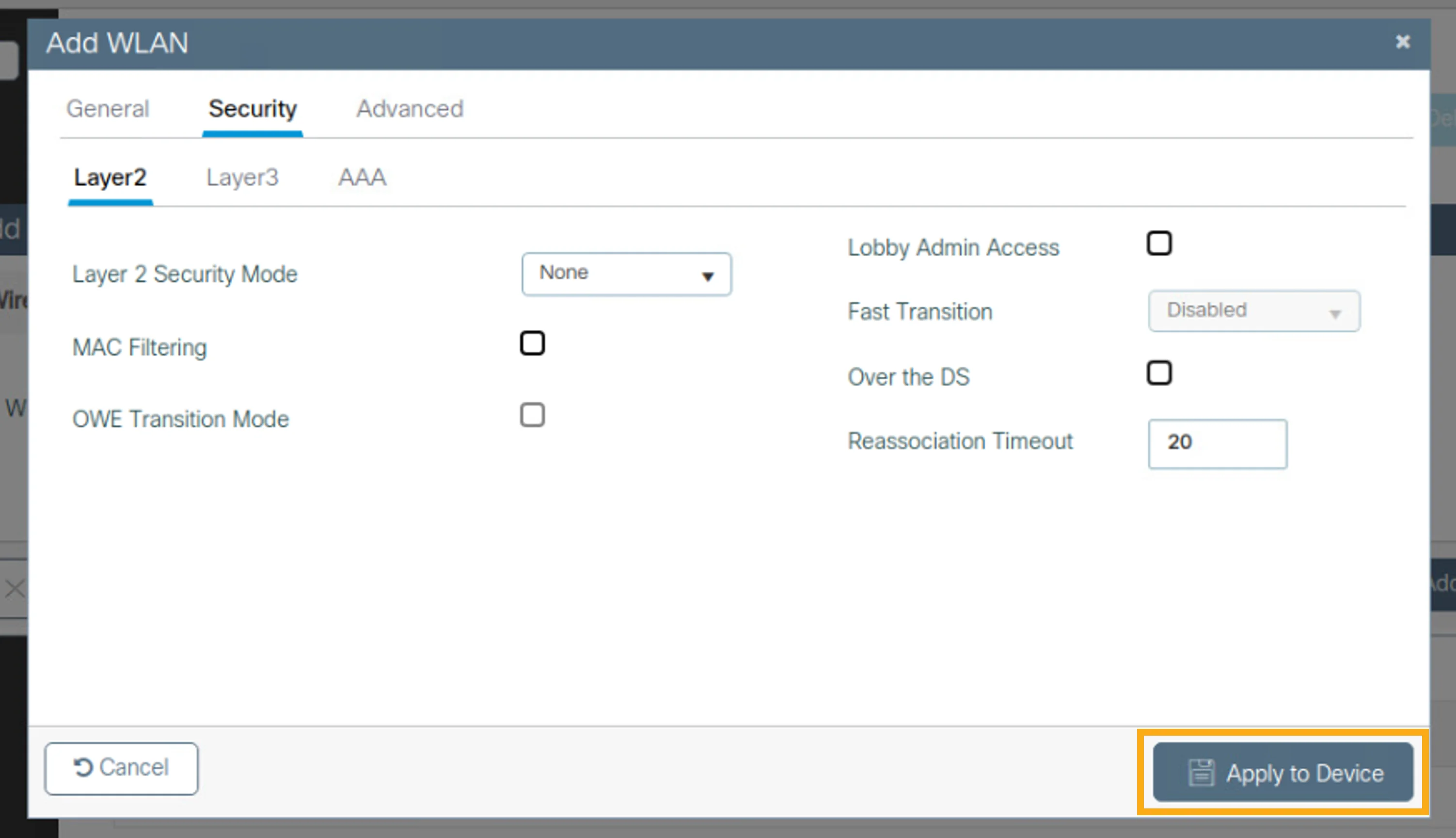
Click Apply to Device to apply Layer 2 security settings to the device. You will get a Configuration Successfully Applied message.
按一下 Apply to Device 將第 2 層安全性設定套用到裝置。你會看到 Configuration Successfully Applied 訊息。
Map a WLAN to a VLAN
將 WLAN 對應到 VLAN
Now that you are back at the Add WLAN window, map the created WLAN to a VLAN with specific policy settings.
現在你已回到 Add WLAN 視窗,請將建立的 WLAN 依照特定原則設定對應到一個 VLAN。
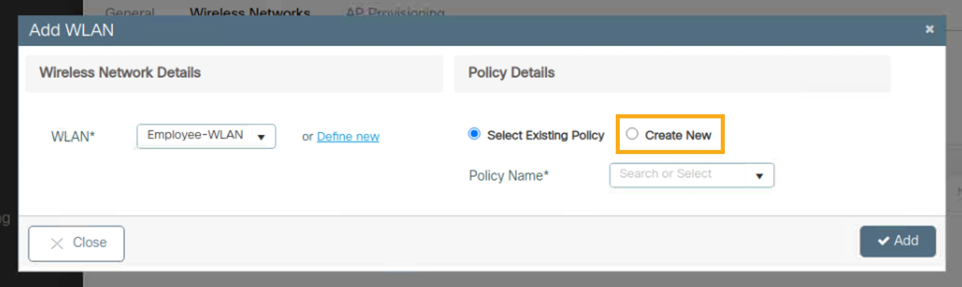
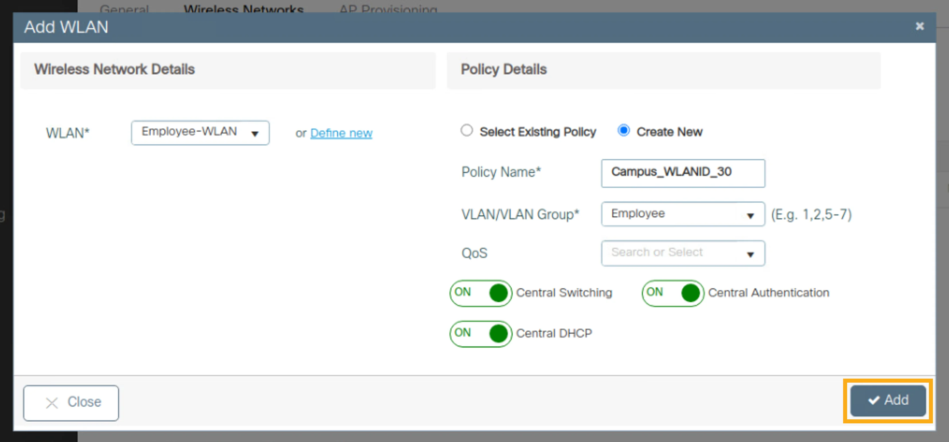
Under Policy Details, click Create New and map the created WLAN to a VLAN using the following policy settings:
在 Policy Details 下,按一下 Create New,並使用下列原則設定將建立的 WLAN 對應到一個 VLAN:
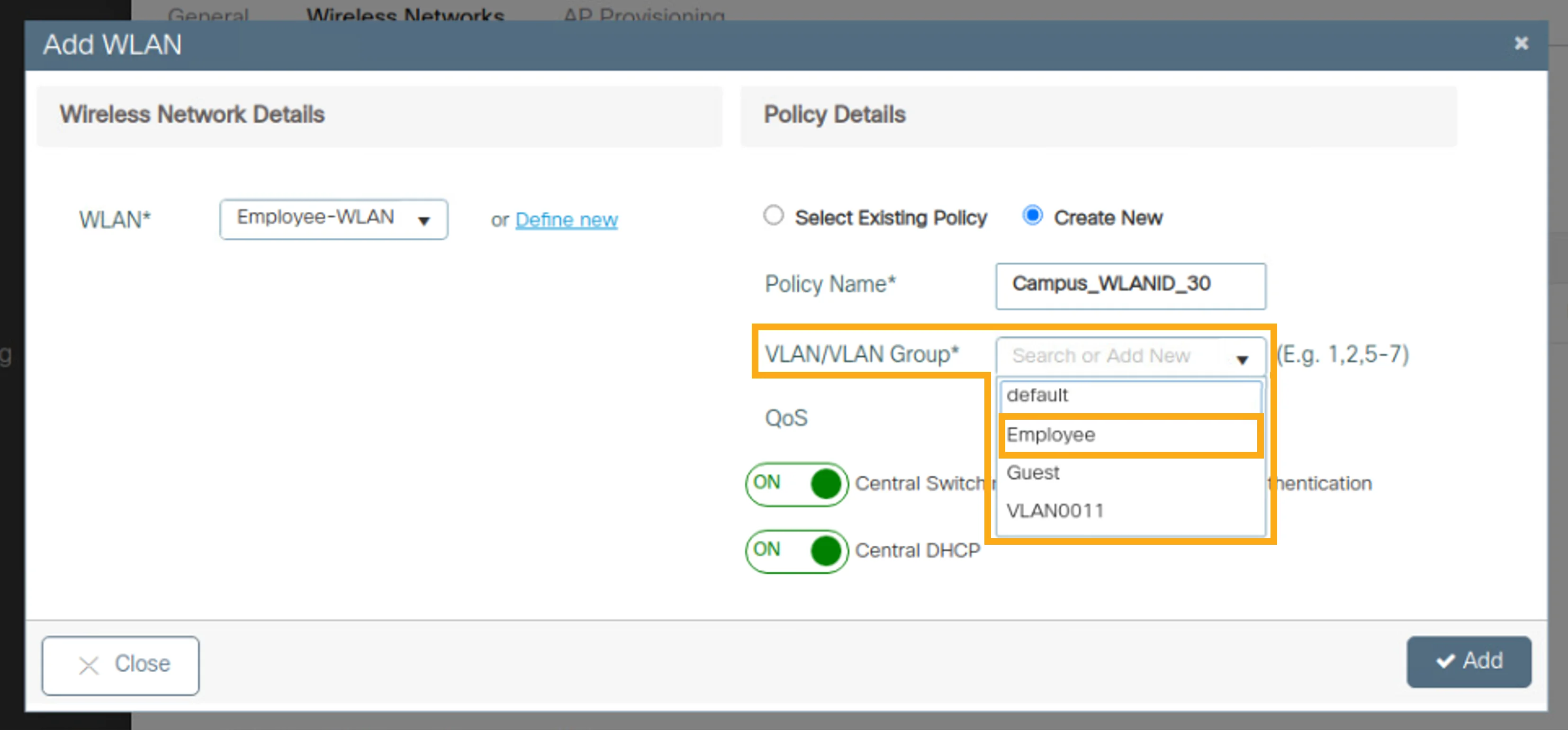
Policy Name Policy Name | Campus_WLANID_30 Campus_WLANID_30 |
VLAN/VLAN Group VLAN/VLAN Group | Employee Employee |
In particular, perform the following procedure to map the WLAN to the Employee VLAN (VLAN 30):
請依照下列程序,將此 WLAN 對應到 Employee VLAN(VLAN 30):
- In the Policy Details pane on the right, click Create New.在右側的 Policy Details 窗格中,按一下 Create New。
- In the VLAN/VLAN Group drop-down list, choose Employee.在 VLAN/VLAN Group 下拉式清單中,選擇 Employee。
Click Add to add the configured WLAN.
按一下 Add 以新增已設定的 WLAN。
Add APs to the Location
為位置新增 AP
You are now back at the Location page.
你現在已回到 Location 頁面。
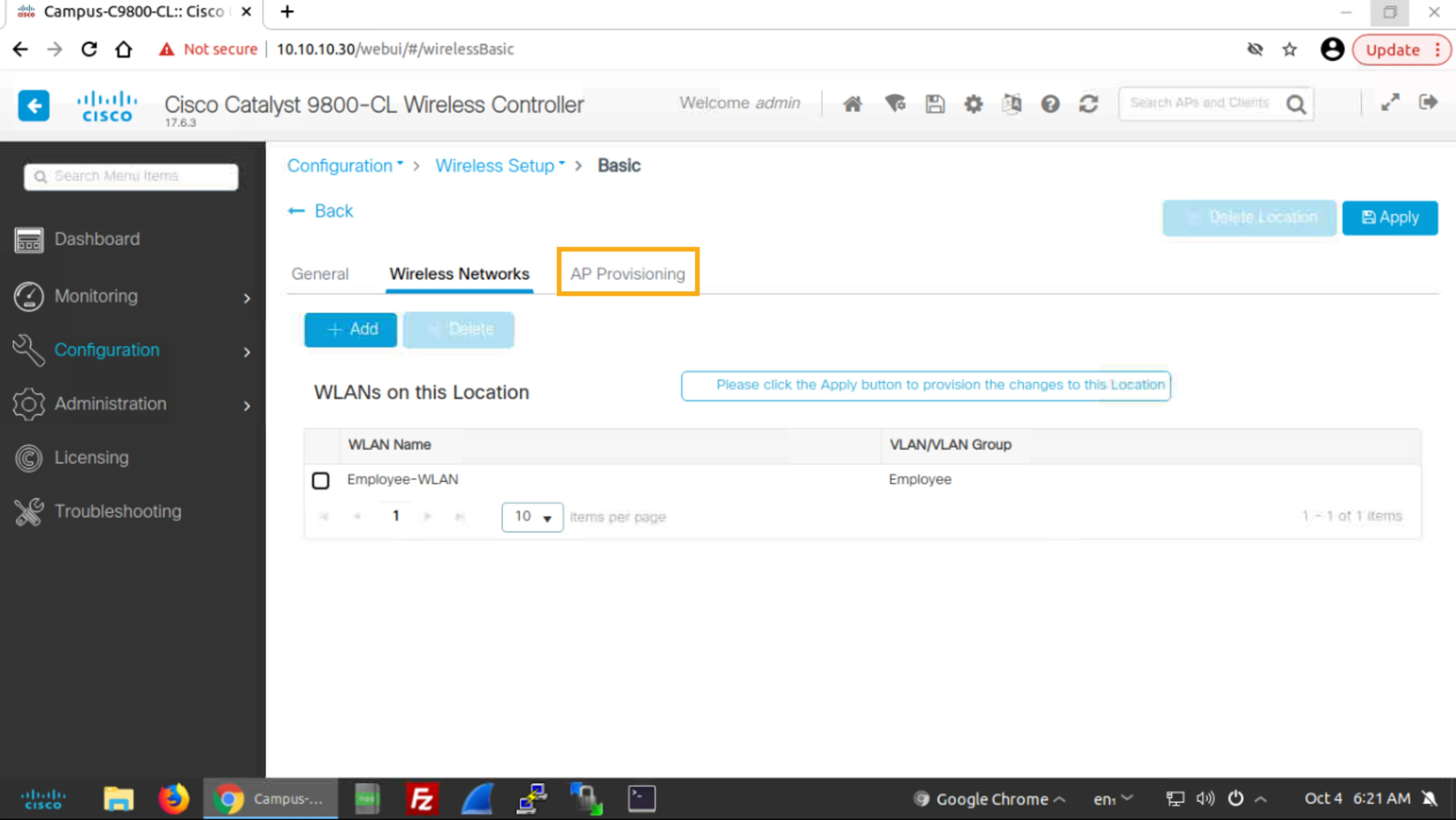
Click the AP Provisioning tab to add the two available APs to the location.
按一下 AP Provisioning 標籤頁,將兩個可用的 AP 新增到該位置。
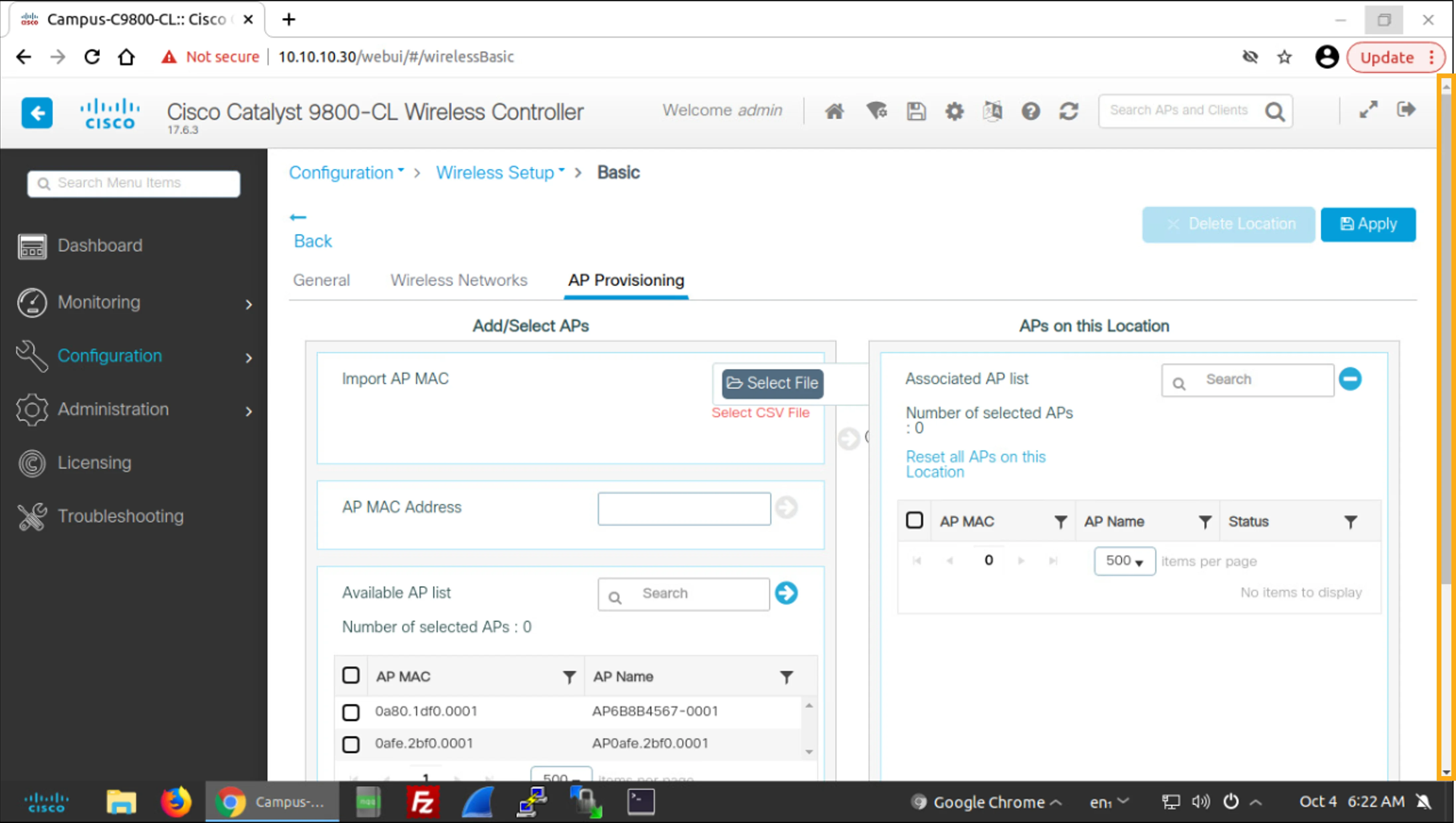
Click in the scroll bar area to move down the page so that you can see the full list of available APs. You can see two available APs.
按一下捲軸區域向下捲動頁面,即可看到完整的可用 AP 清單。你可以看到兩個可用的 AP。
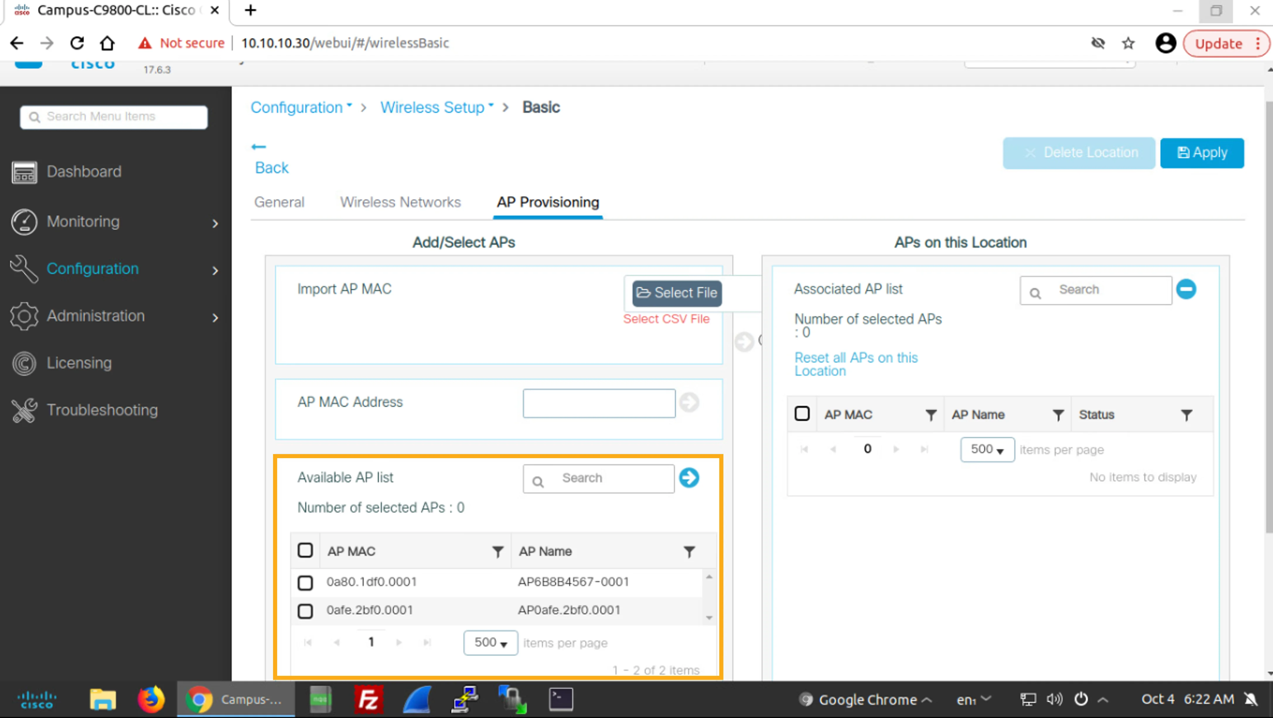
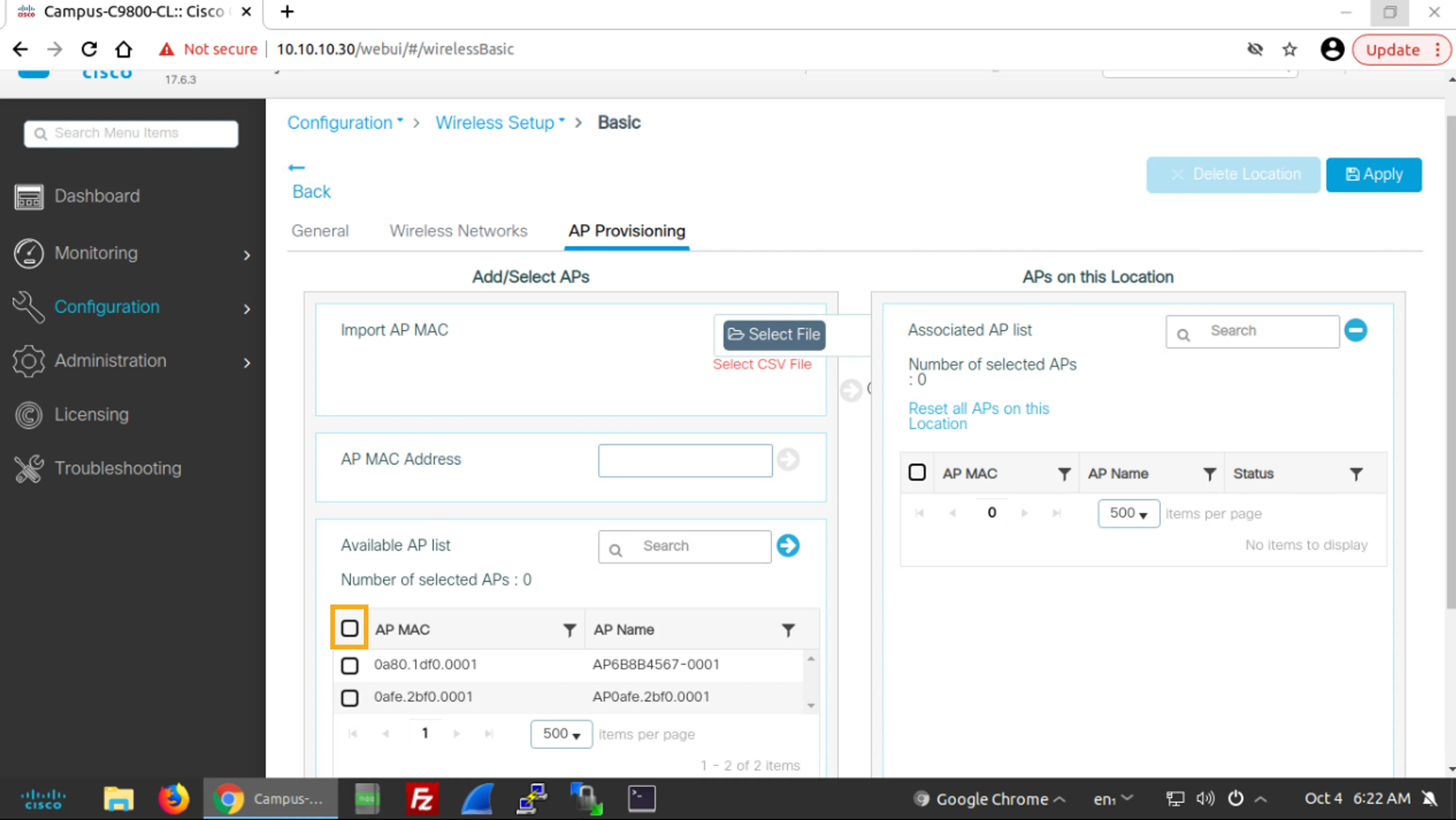
In the Add/Select APs pane on the left, In the Available AP list section, check the check box to the left of the AP MAC in the table header row to simultaneously select both available APs.
在左側的 Add/Select APs 窗格中,於 Available AP list 區段中,勾選表格標題列中 AP MAC 左側的核取方塊,同時選取兩個可用的 AP。
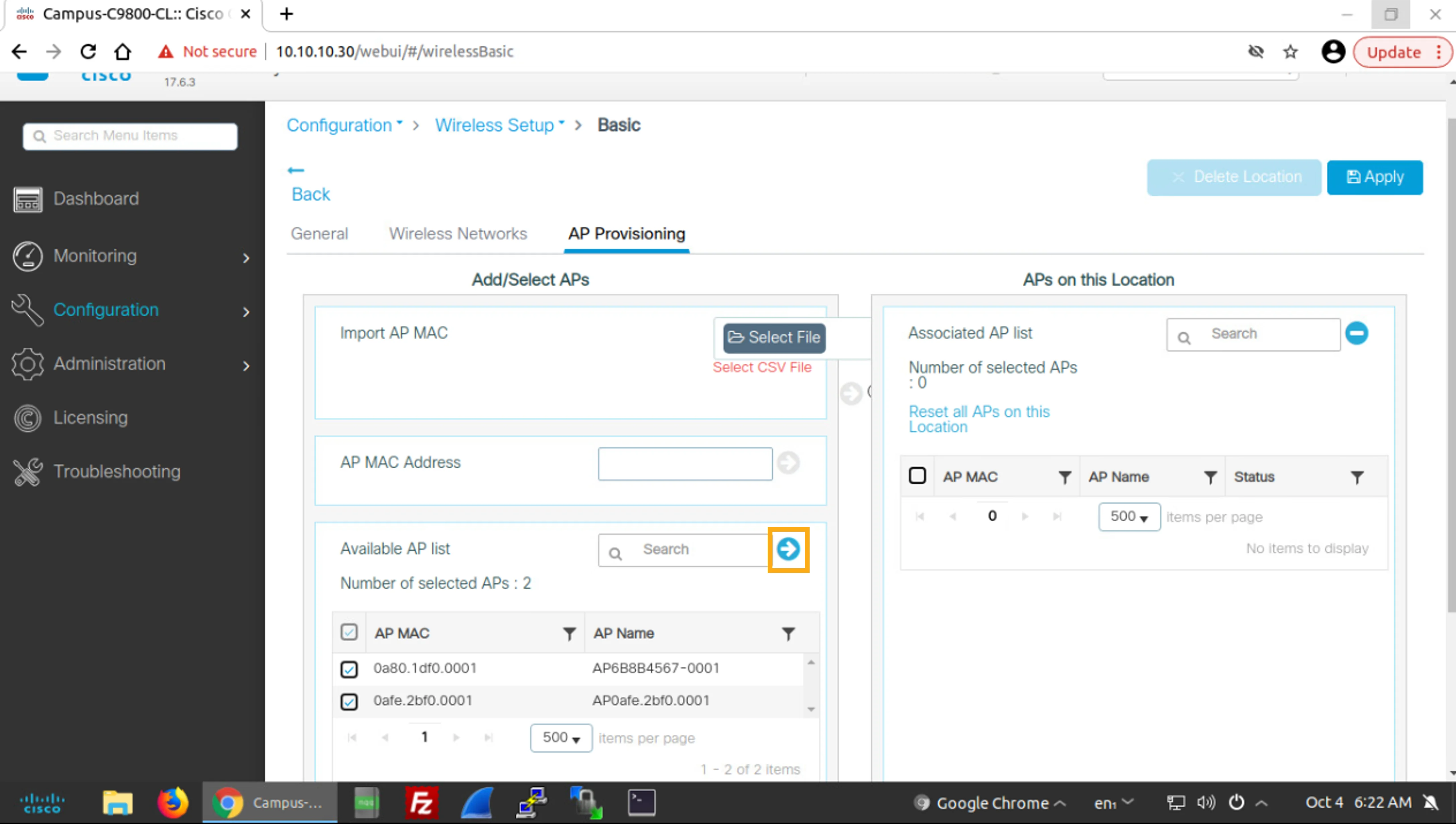
In the Available AP list section, click the blue arrow pointing to the right to add the selected APs to the location.
在 Available AP list 區段中,按一下指向右方的藍色箭頭,將所選的 AP 新增到該位置。
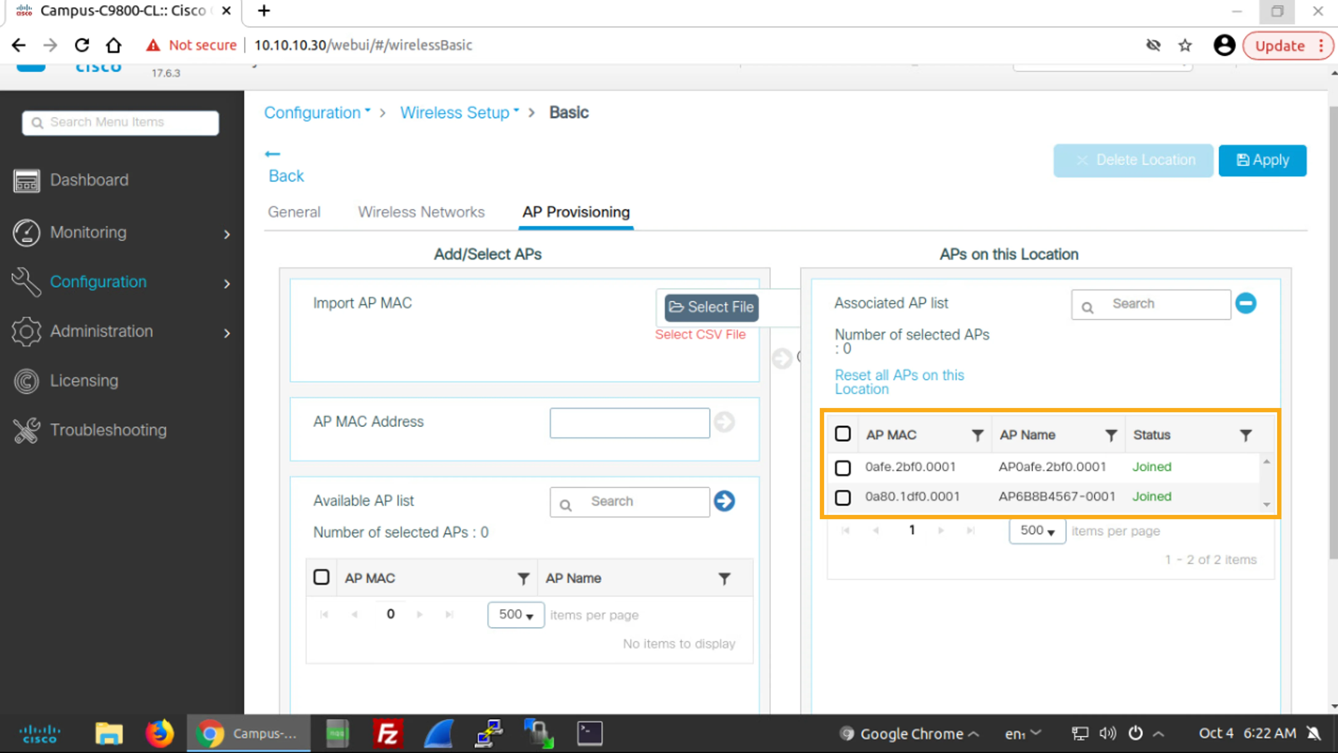
Note that the selected APs have been moved from the Available AP list to the APs on this Location pane on the right, to the Associated AP list section.
請注意,所選的 AP 已從 Available AP list 移到右側 APs on this Location 窗格中的 Associated AP list 區段。
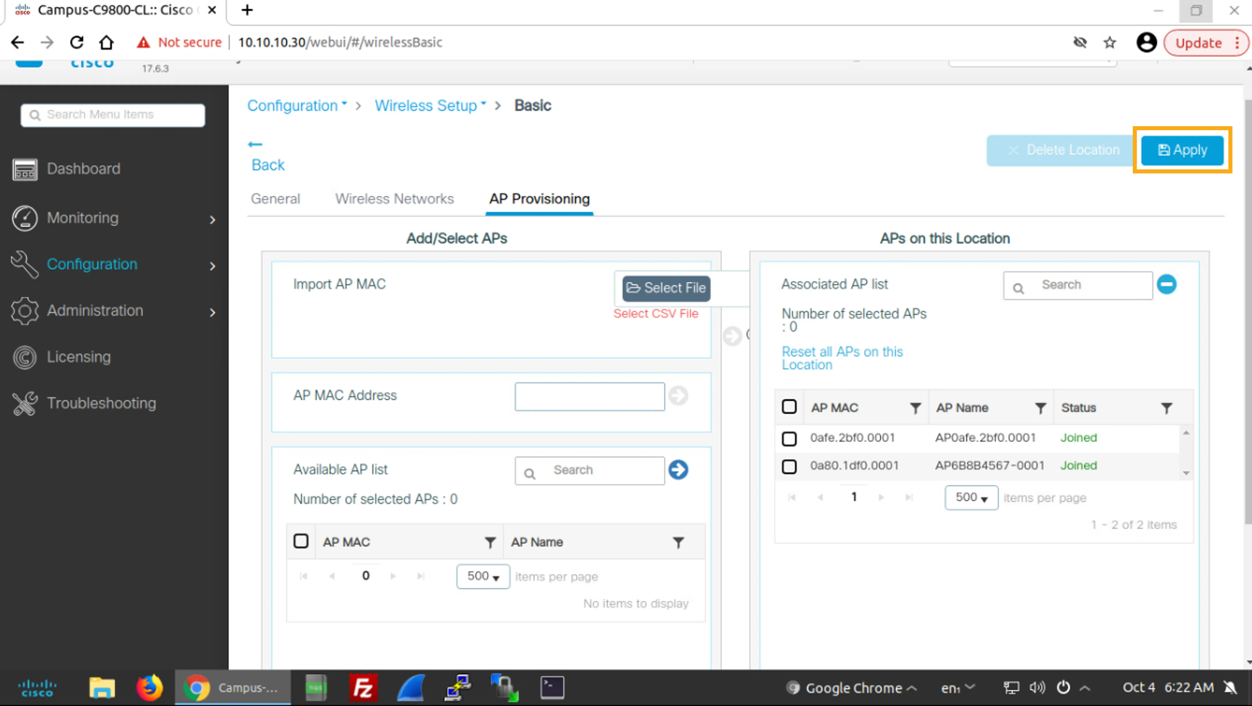
Click Apply to apply your configuration to the WLC.
按一下 Apply,將你的設定套用到 WLC。
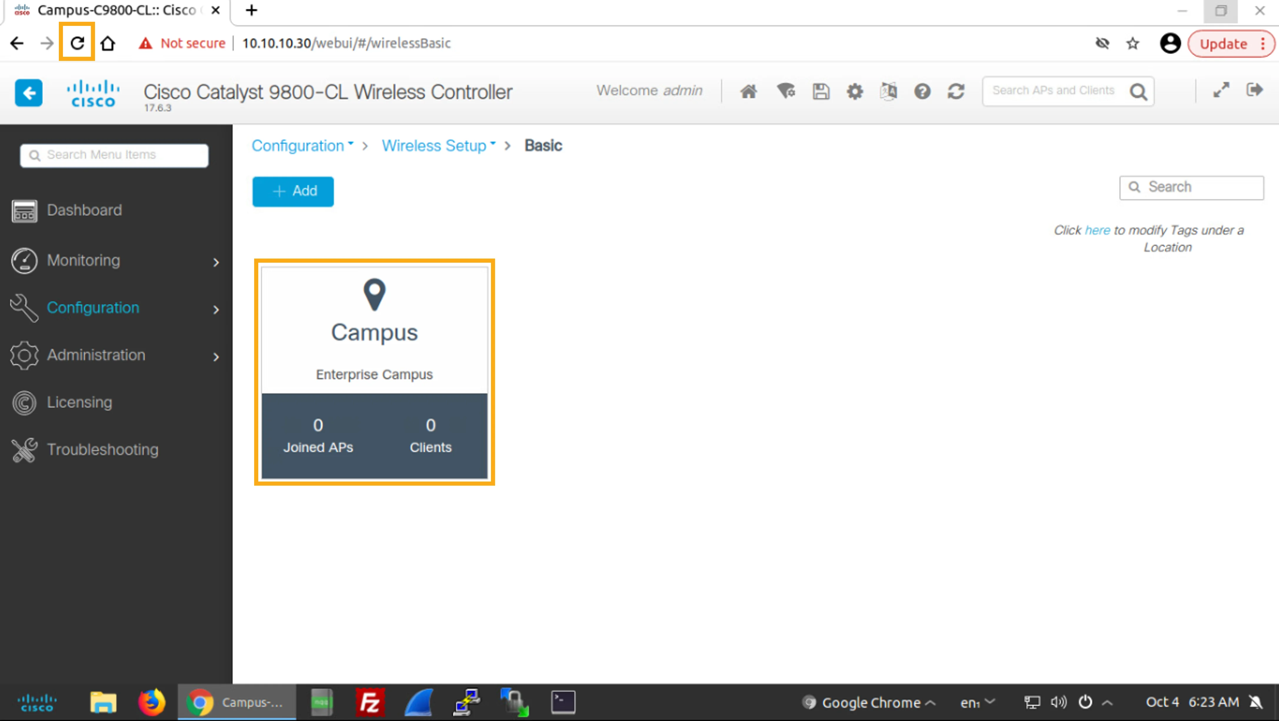
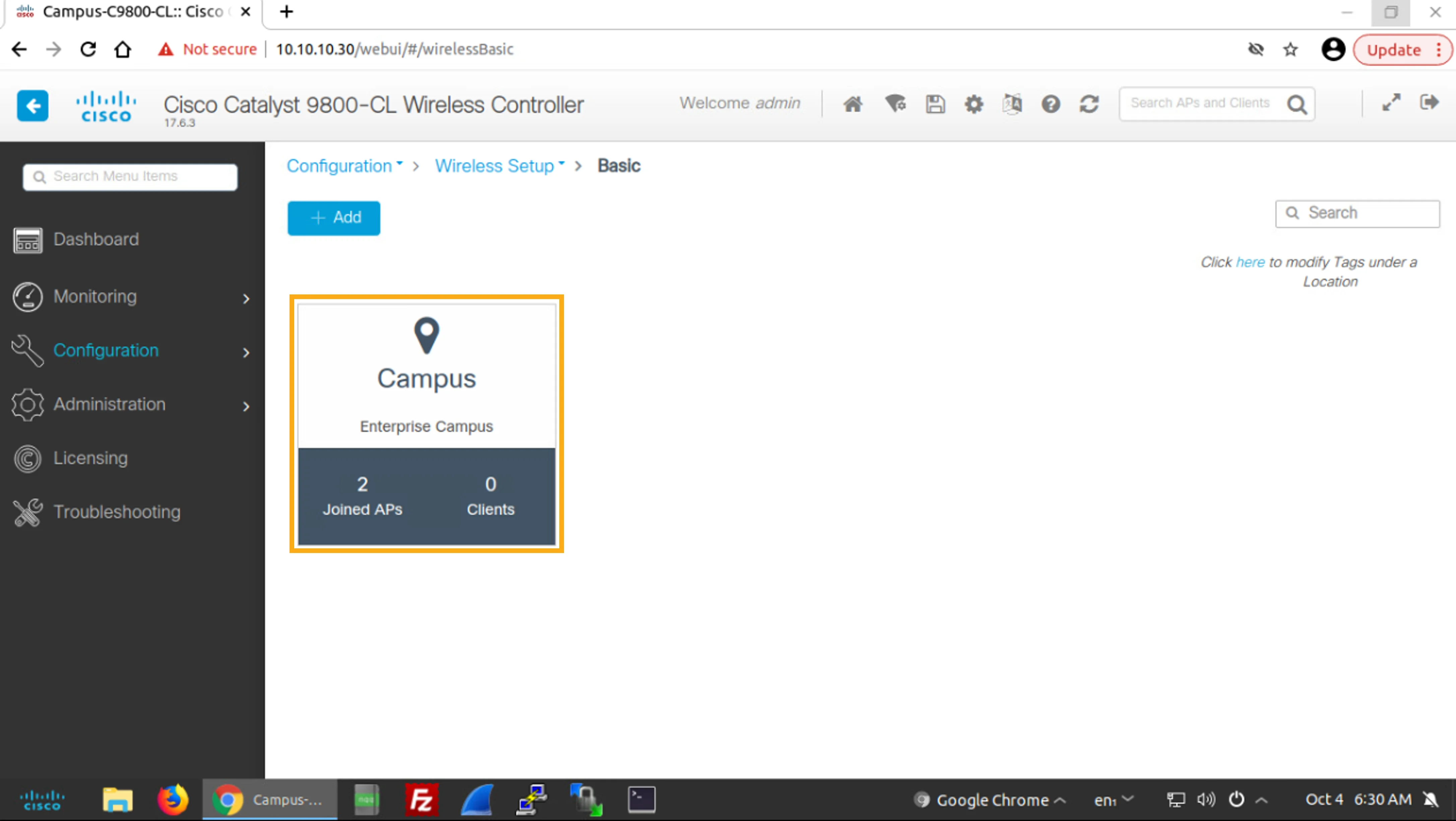
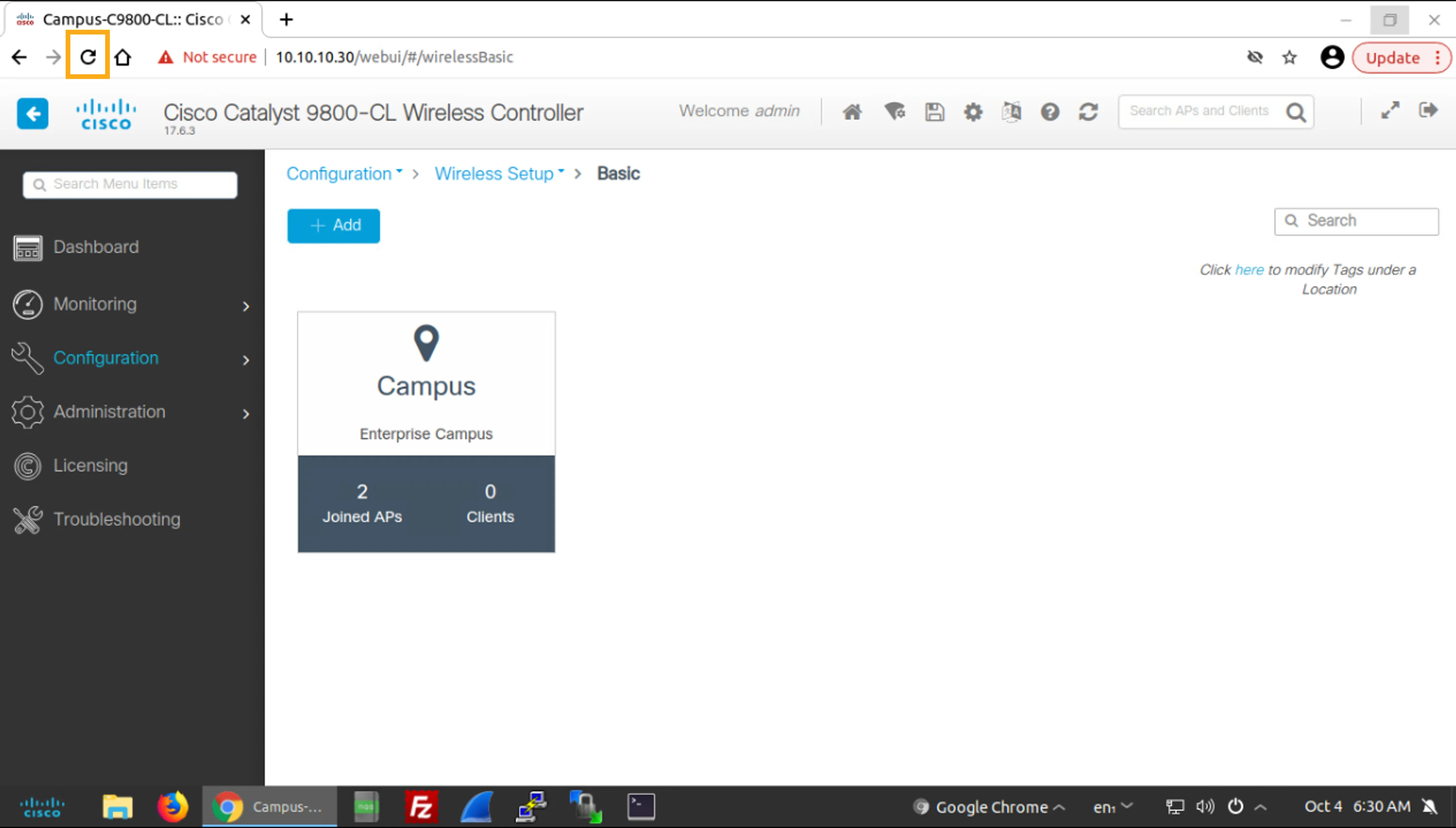
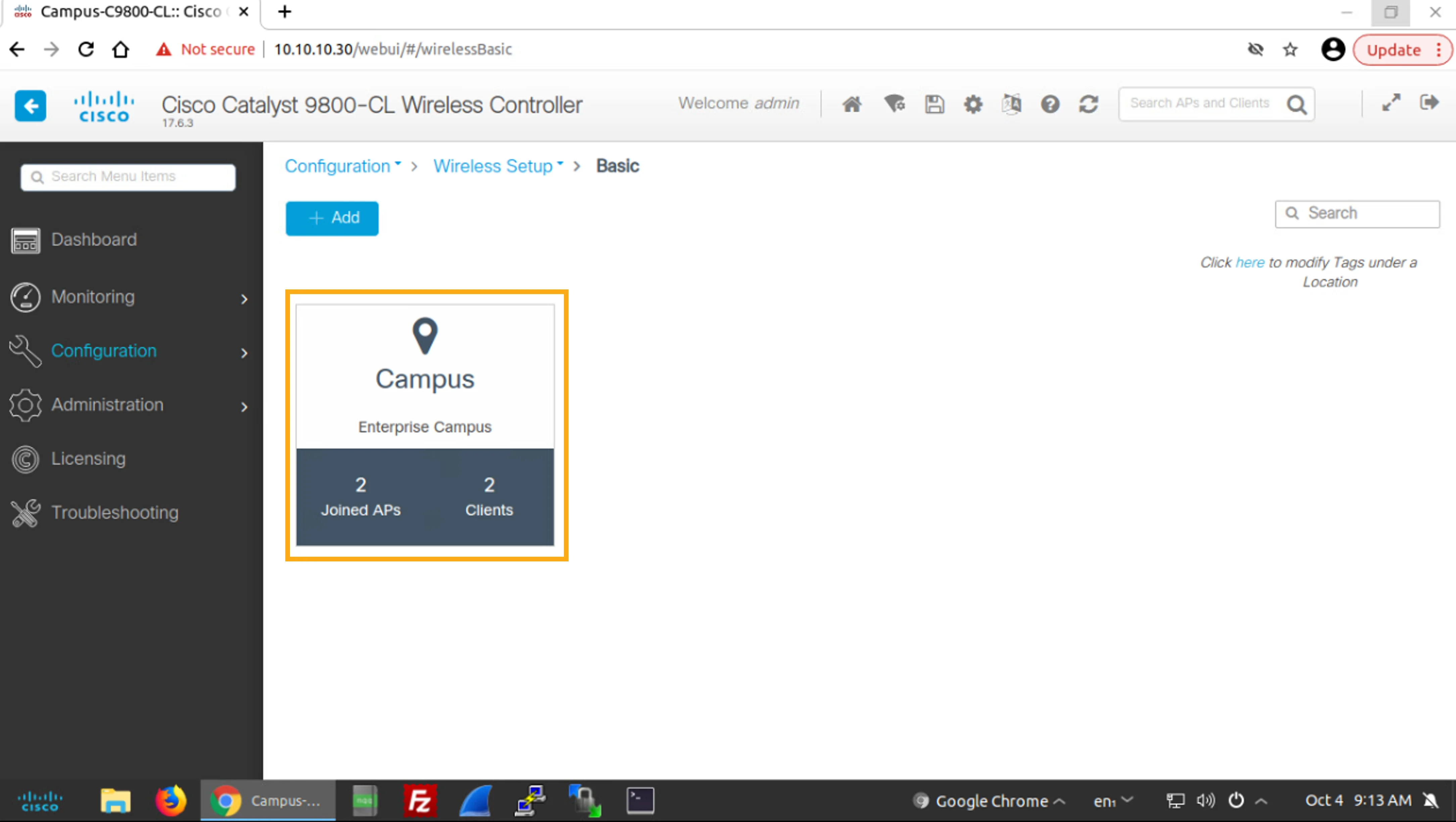
You are now back at the Configuration > Wireless > Basic page that shows the configured locations. Note that the Campus location shows zero Joined APs and zero Clients. Wait for about one minute and then refresh the page. Verify that the number of Joined APs changes from 0 to 2.
你現在回到顯示已設定位置的 Configuration > Wireless > Basic 頁面。請注意,Campus 位置顯示 Joined APs 為零,Clients 也為零。請等待約一分鐘,然後重新整理頁面。驗證 Joined APs 的數量是否從 0 變為 2。
The basic wireless setup page looks like this immediately after applying the configuration in the previous step. Click the browser Reload icon to refresh the page.
在前一步套用設定後,基本無線設定頁面會立即顯示如下畫面。按一下瀏覽器的 Reload 圖示以重新整理頁面。
After refreshing the page, you can see two Joined APs in the Campus location:
重新整理頁面後,你可以在 Campus 位置看到兩個 Joined APs:
You finished the configuration of an open wireless network.
你已完成開放式無線網路的設定。
Task 2: Verify Wireless Network Connectivity
任務 2:驗證無線網路連線
After configuring wireless network services, you should always make sure that you can access the network and test IP connectivity.
設定無線網路服務後,你應該永遠確認可以存取網路並測試 IP 連線。
You will now verify proper operation of the wireless network that you configured in the previous task.
你現在將驗證前一項任務中所設定的無線網路是否正常運作。
First, you will connect to the wireless network from two client PCs (Client PC 1 and Client PC 2). Then you will verify IP connectivity, and finally, you will monitor the client connections from the Campus WLC web GUI.
首先,你會從兩台用戶端 PC(用戶端 PC 1 與用戶端 PC 2)連線到無線網路。接著你會驗證 IP 連線,最後你會從 Campus WLC 網頁 GUI 監控用戶端連線。
Activity
活動
Connect Client PC 1 to the WLAN
將用戶端 PC 1 連線到 WLAN
First, you will connect Client PC 1 to WLAN.
首先,你會將用戶端 PC 1 連線到 WLAN。
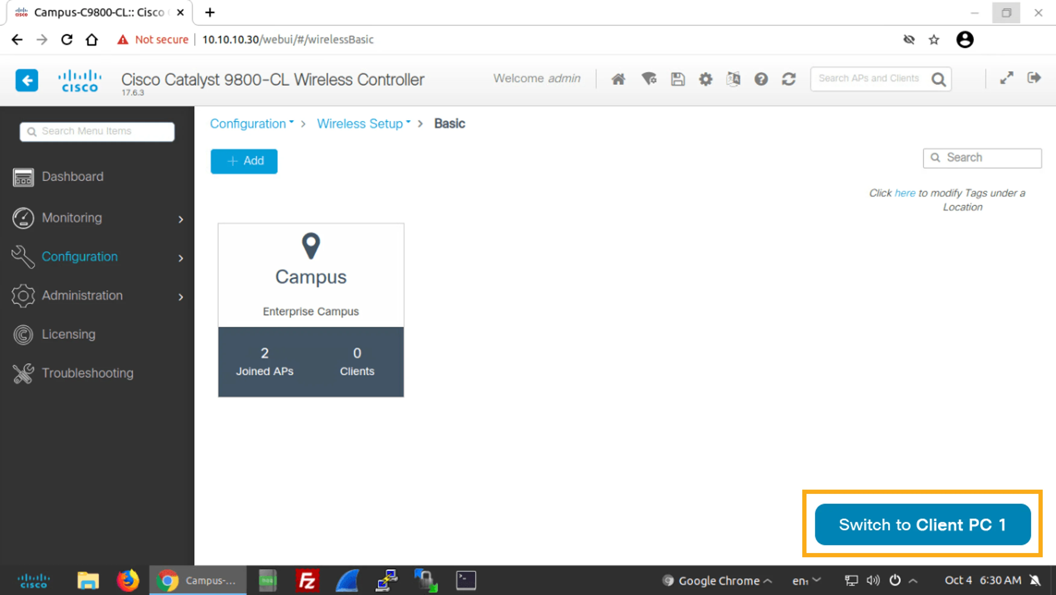
Click the Switch to Client PC 1 button, which is located at the bottom-right corner of the desktop to switch from the Admin PC to Client PC 1.
按一下位於桌面右下角的 Switch to Client PC 1 按鈕,從管理用 PC 切換到用戶端 PC 1。
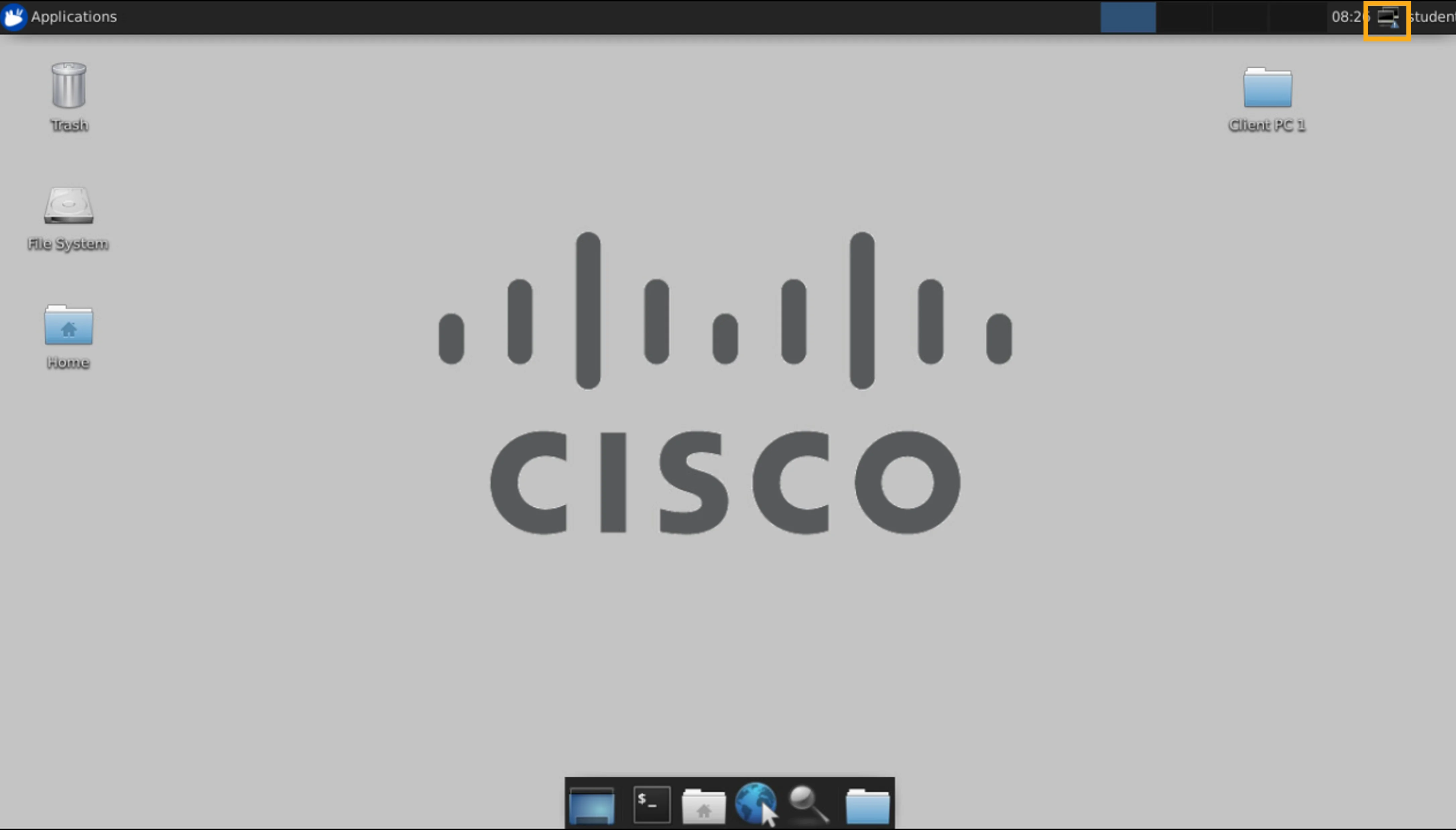
On Client PC 1, click the Network icon, which is in the top-right corner of the desktop.
在 Client PC 1 上,按一下位於桌面右上角的 Network 圖示。
In the Wicd Network Manager window, click Refresh to scan for available networks.
在 Wicd Network Manager 視窗中,按一下 Refresh 掃描可用的網路。
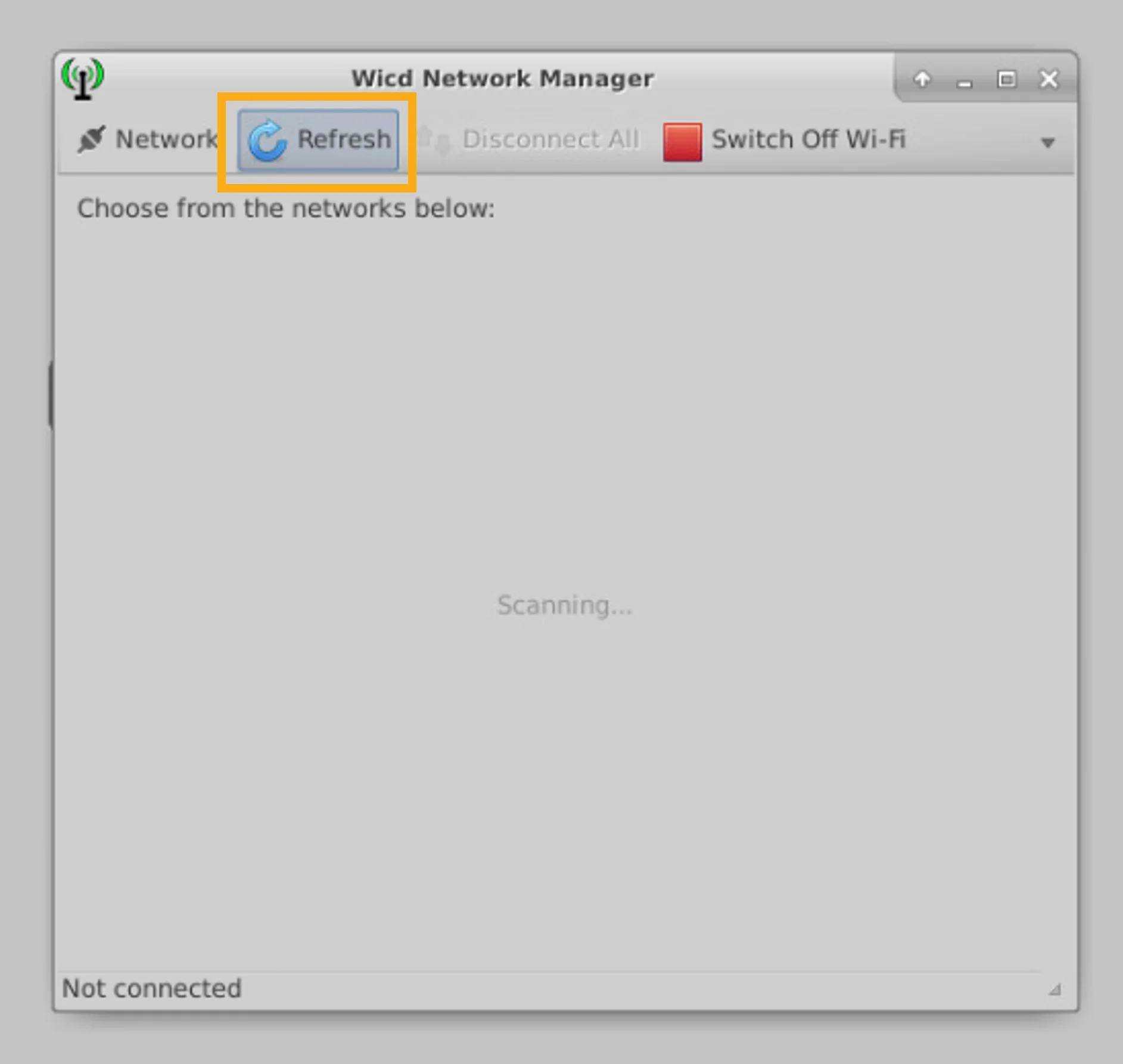
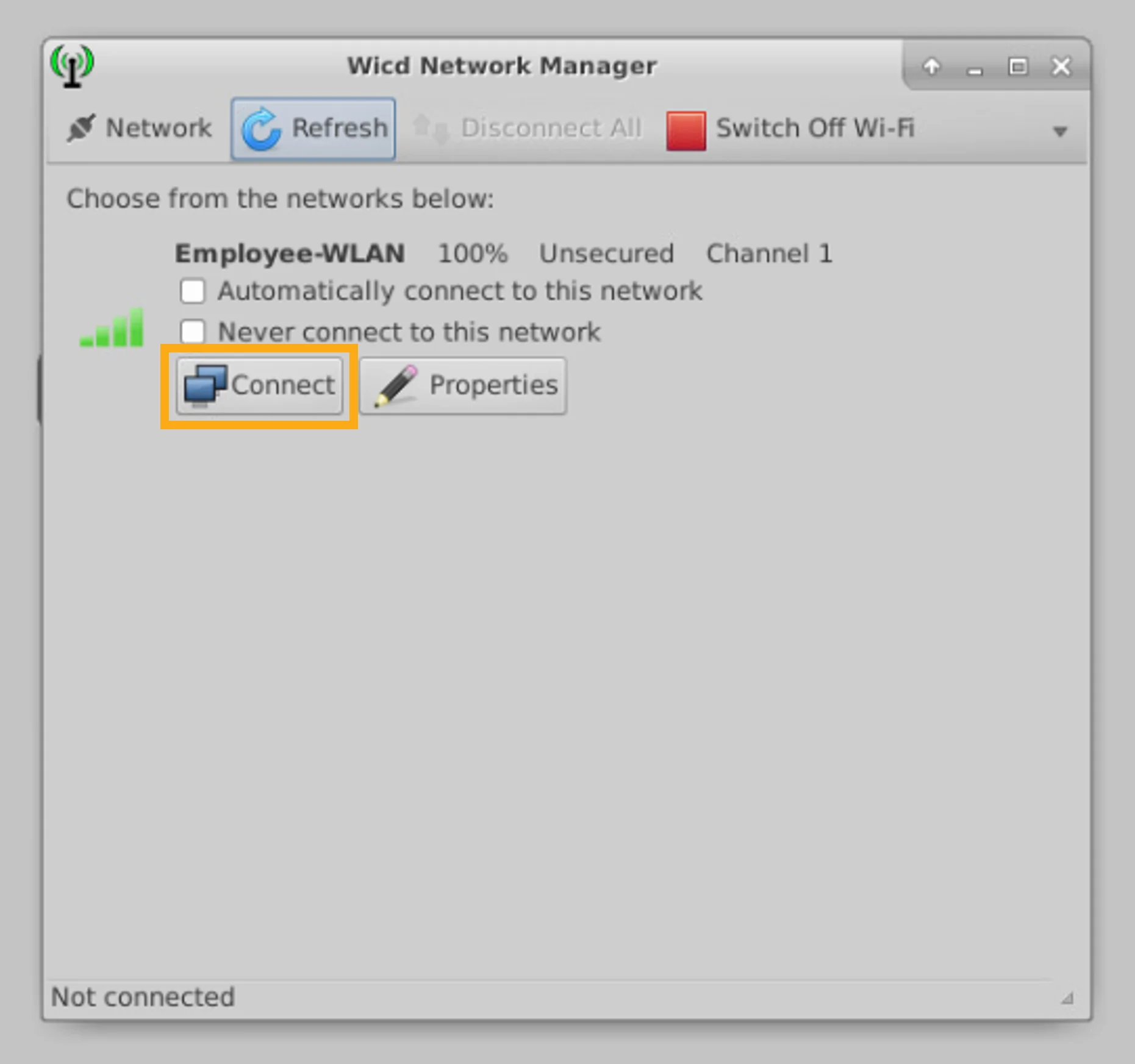
The Employee-WLAN network is shown. Click Connect to connect to this WLAN.
畫面會顯示 Employee-WLAN 網路。按一下 Connect 連線到此 WLAN。
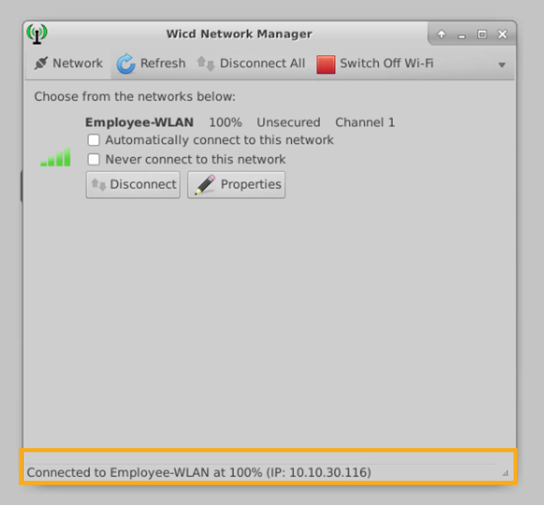
Verify that Client PC 1 is connected to the Employee-WLAN and that the client was assigned an IP address of network 10.10.30.0/24.
驗證用戶端 PC 1 已連線到 Employee-WLAN,並確認該用戶端已被指派 10.10.30.0/24 網路的 IP 位址。
Connect Client PC 2 to the WLAN
將用戶端 PC 2 連線到 WLAN
Now you will connect Client PC 2 to WLAN.
現在你將把用戶端 PC 2 連線到 WLAN。
Click the Switch to Client PC 2 button, which is located at the bottom-right corner of the desktop to switch from Client PC 1 to Client PC 2.
按一下位於桌面右下角的 Switch to Client PC 2 按鈕,從用戶端 PC 1 切換到用戶端 PC 2。
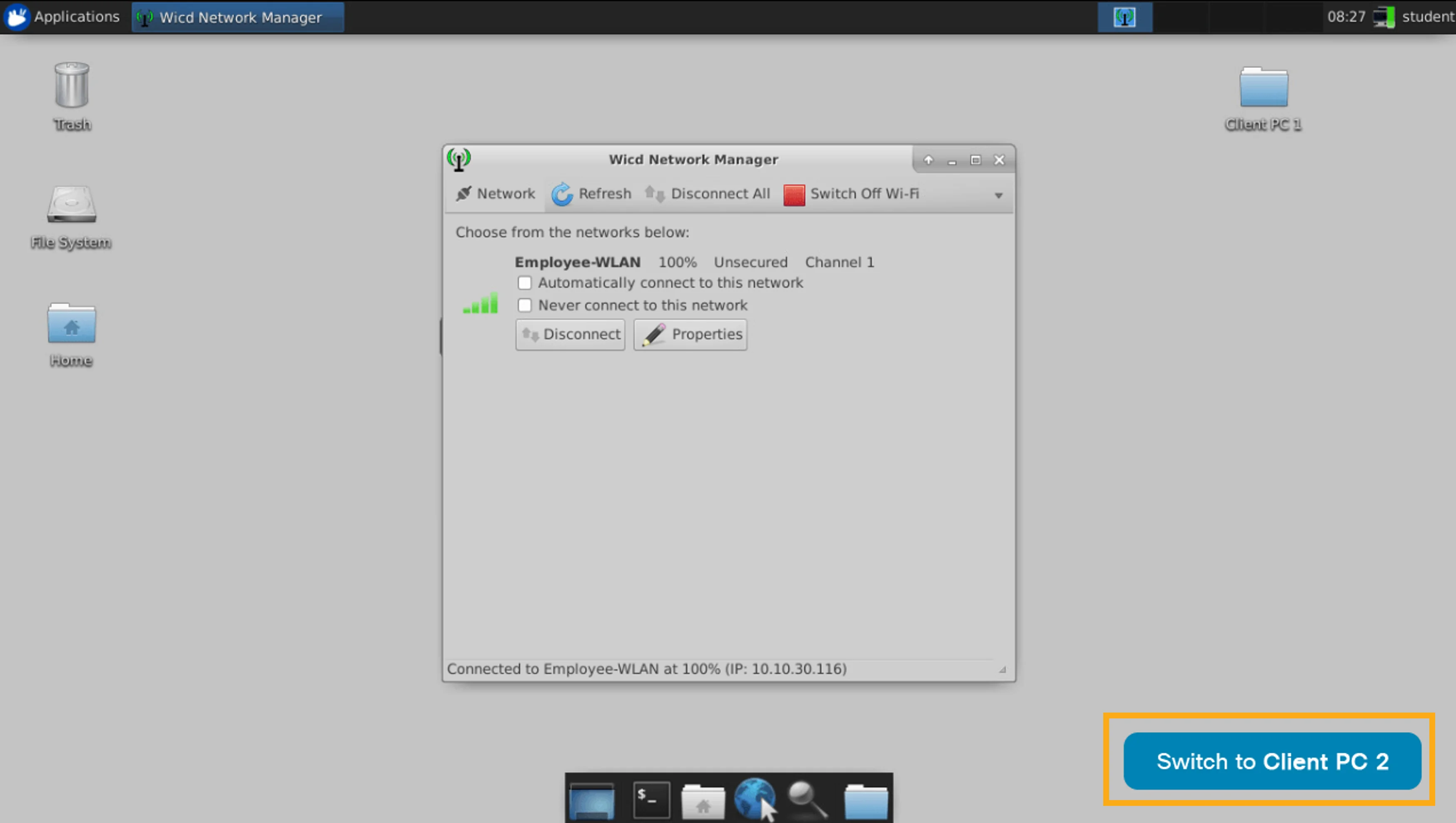
On Client PC 2, connect to the WLAN called Employee-WLAN by repeating the same procedure that you performed on Client PC 1.
在 Client PC 2 上,透過重複你在用戶端 PC 1 上執行過的相同程序,連線到名為 Employee-WLAN 的 WLAN。
Click the Network icon that is in the top-right corner of the desktop.
按一下位於桌面右上角的 Network 圖示。
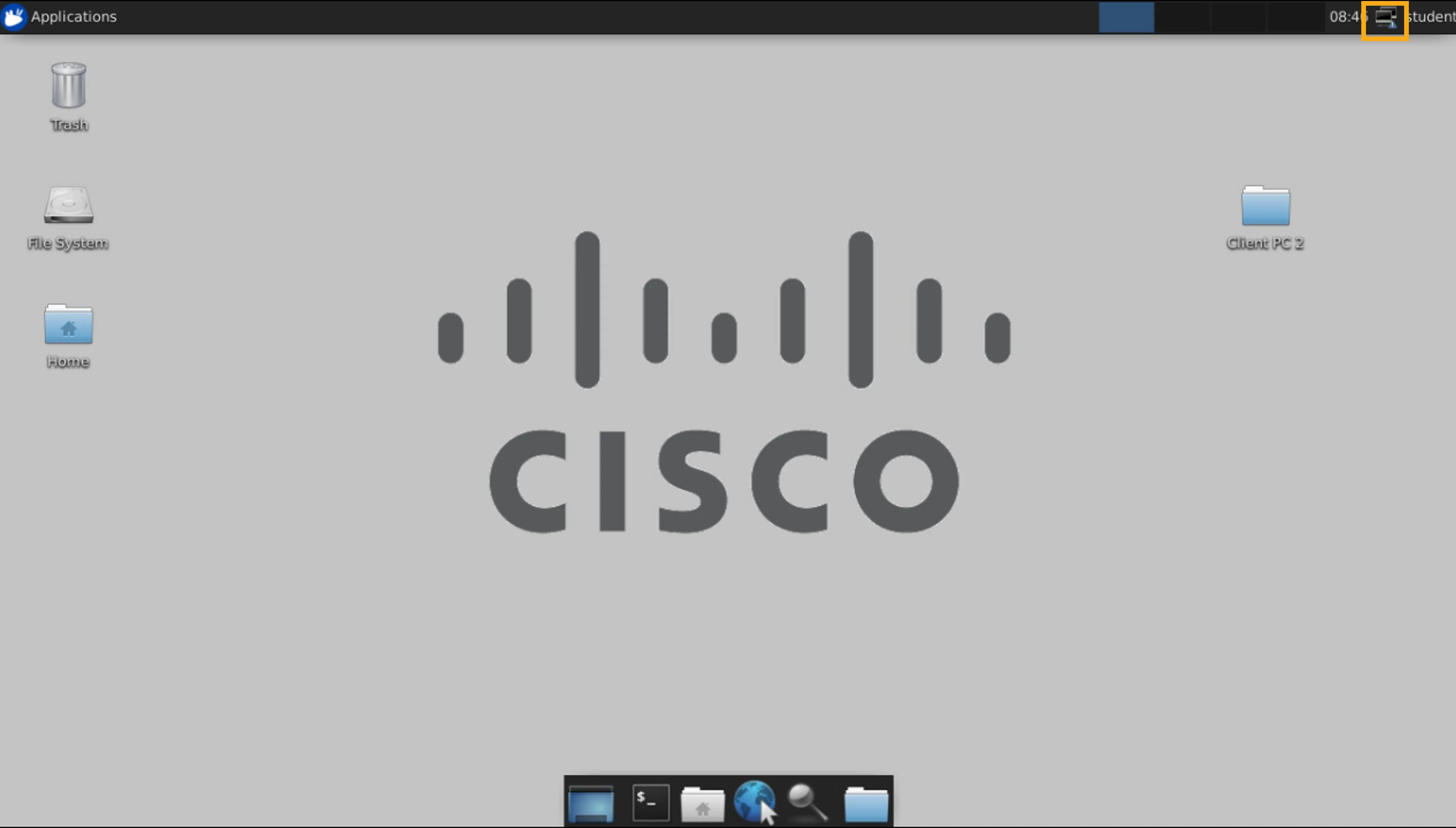
In the Wicd Network Manager window, click Refresh to scan for available networks.
在 Wicd Network Manager 視窗中,按一下 Refresh 掃描可用的網路。
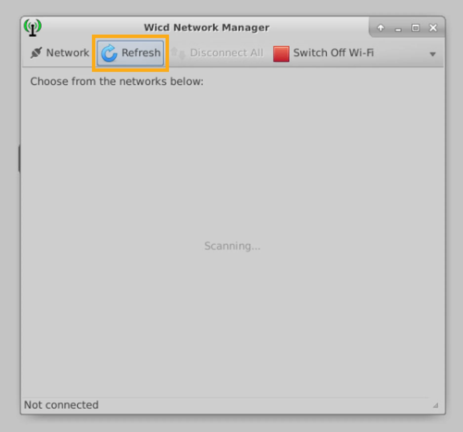
The Employee-WLAN network is shown. Click Connect to connect to this WLAN.
畫面會顯示 Employee-WLAN 網路。按一下 Connect 連線到此 WLAN。
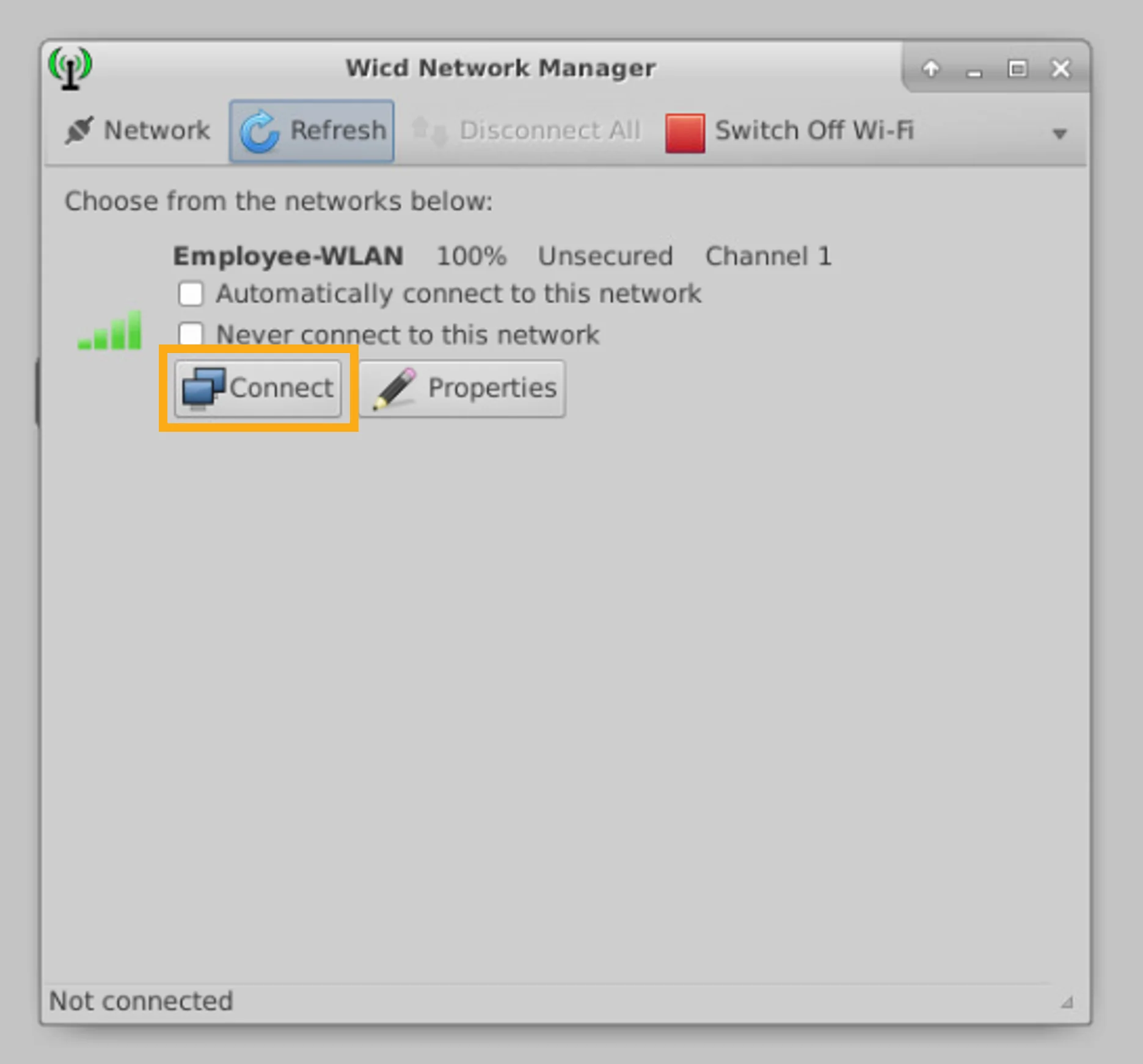
Verify that Client PC 2 is connected to the Employee-WLAN and that the client was assigned an IP address of network 10.10.30.0/24.
驗證用戶端 PC 2 已連線到 Employee-WLAN,並確認該用戶端已被指派 10.10.30.0/24 網路的 IP 位址。
Verify the Client PC 2 Network Connectivity
驗證用戶端 PC 2 的網路連線
In the next steps, you will verify network connectivity by pinging the default gateway and Client PC 1.
在接下來的步驟中,你將透過對預設閘道與用戶端 PC 1 執行 ping 來驗證網路連線。
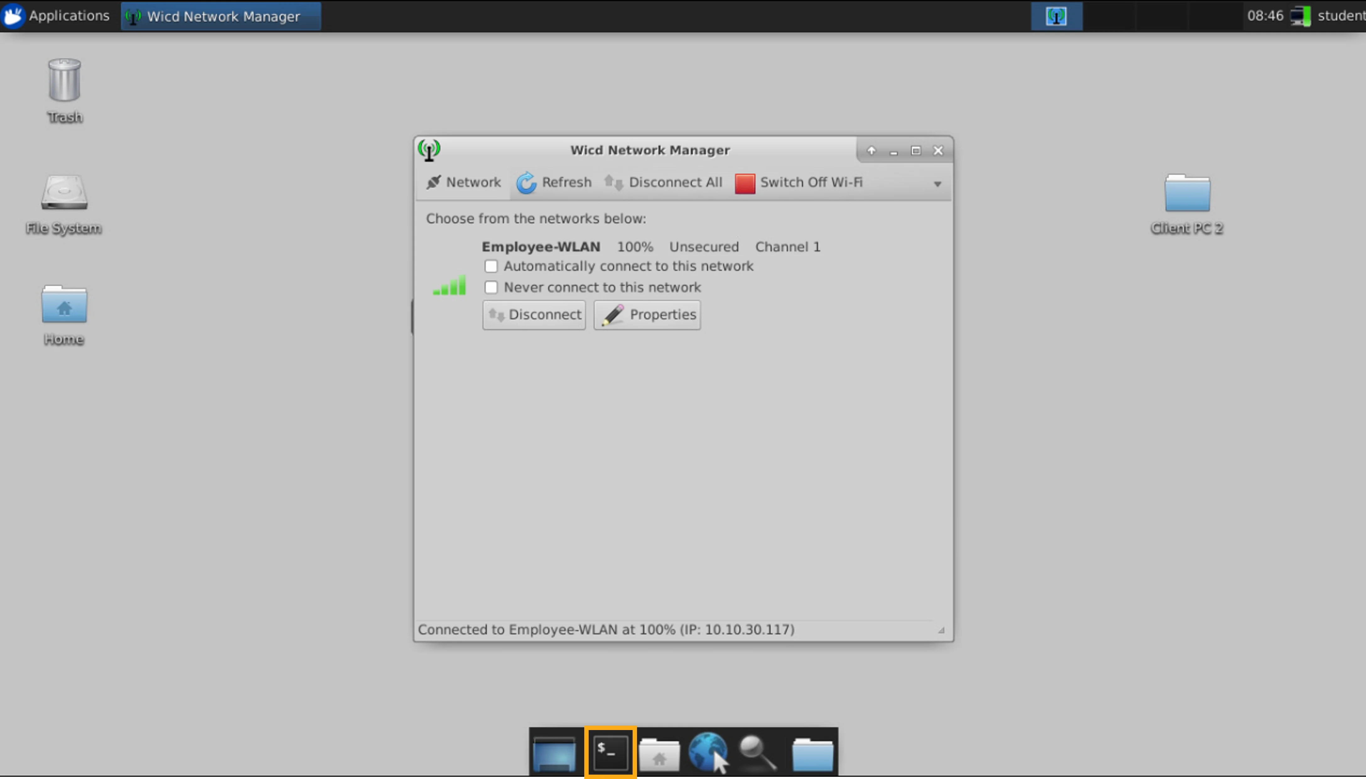
On Client PC 2, open a Terminalwindow, and verify network connectivity by pinging the default gateway at 10.10.30.1. Validate the results.
在用戶端 PC 2 上,開啟 Terminal 視窗,並透過對 10.10.30.1 的預設閘道執行 ping 來驗證網路連線。請驗證結果。
You will see that the first ping timed out, but the following four pings were successful.
你會看到第一次 ping 逾時,但接下來的四次 ping 都成功了。
Perform the following procedure:
請執行下列程序:
- Click the Terminal icon.按一下 Terminal 圖示。
- In the terminal window, enter the
ping 10.10.30.1command. Then, press Enter.在終端機視窗中,輸入ping 10.10.30.1命令,然後按 Enter。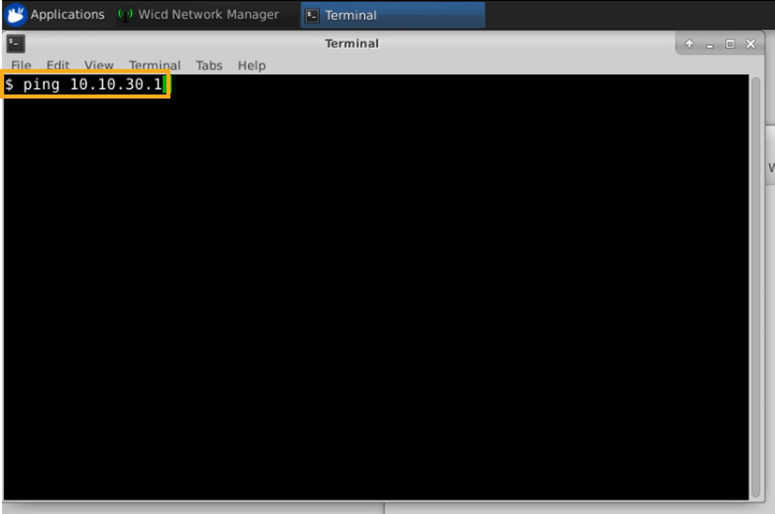
- Verify the result. The first ping timed out, but the following four pings were successful.驗證結果。第一次 ping 逾時,但接下來的四次 ping 都成功了。
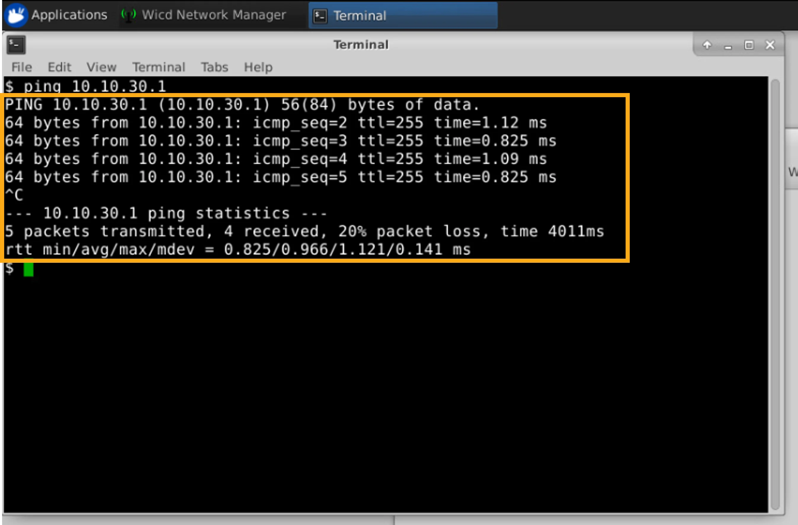
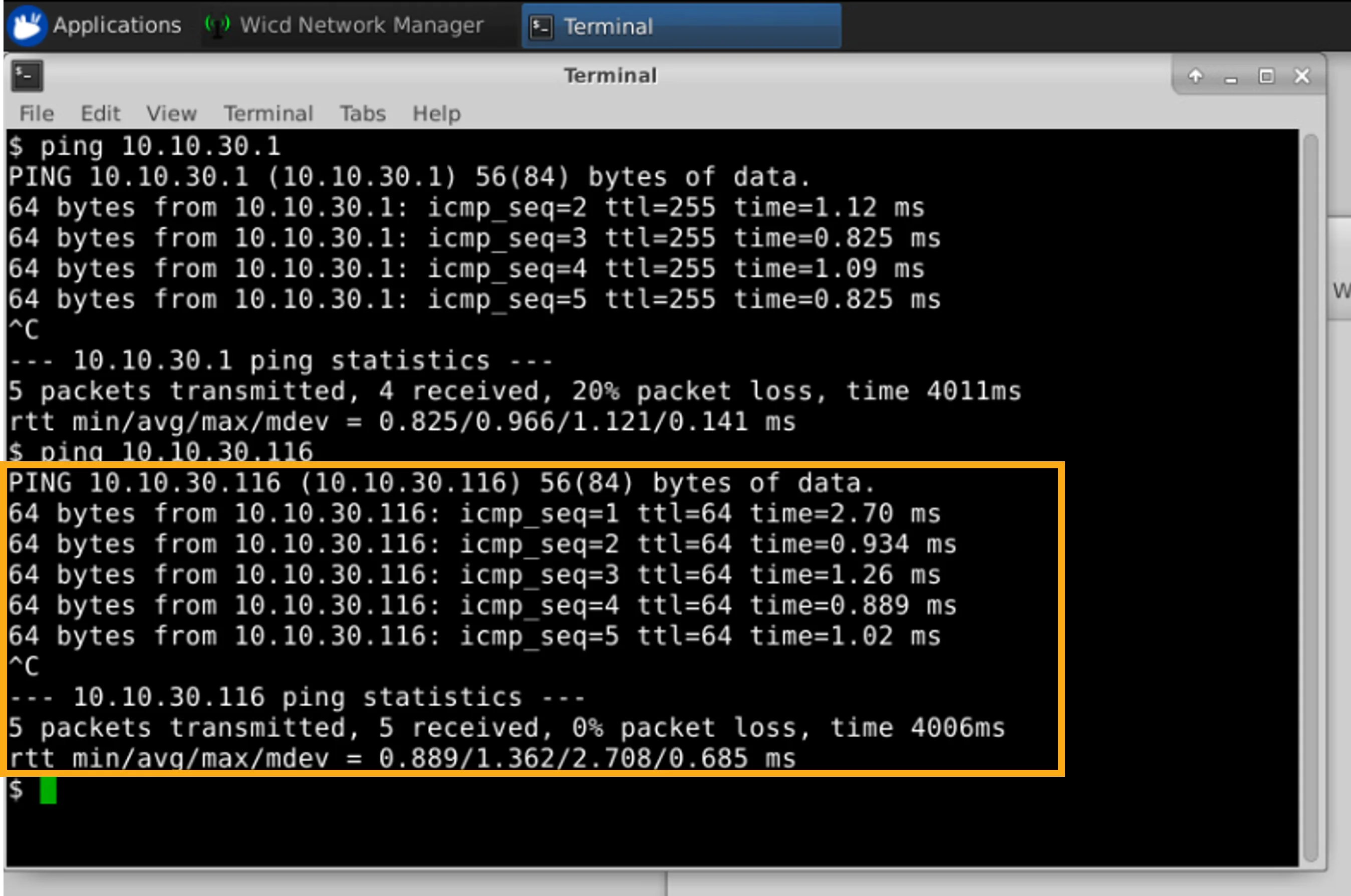
Now, let's verify the connectivity to Client PC 1 at 10.10.30.116.
現在,讓我們驗證與位於 10.10.30.116 的用戶端 PC 1 之間的連線。
You will see that all five pings were successful.
你會看到全部五次 ping 都成功了。
Perform the following procedure:
請執行下列程序:
- In the terminal window, enter the
ping 10.10.30.116command and press Enter.在終端機視窗中,輸入ping 10.10.30.116命令並按 Enter。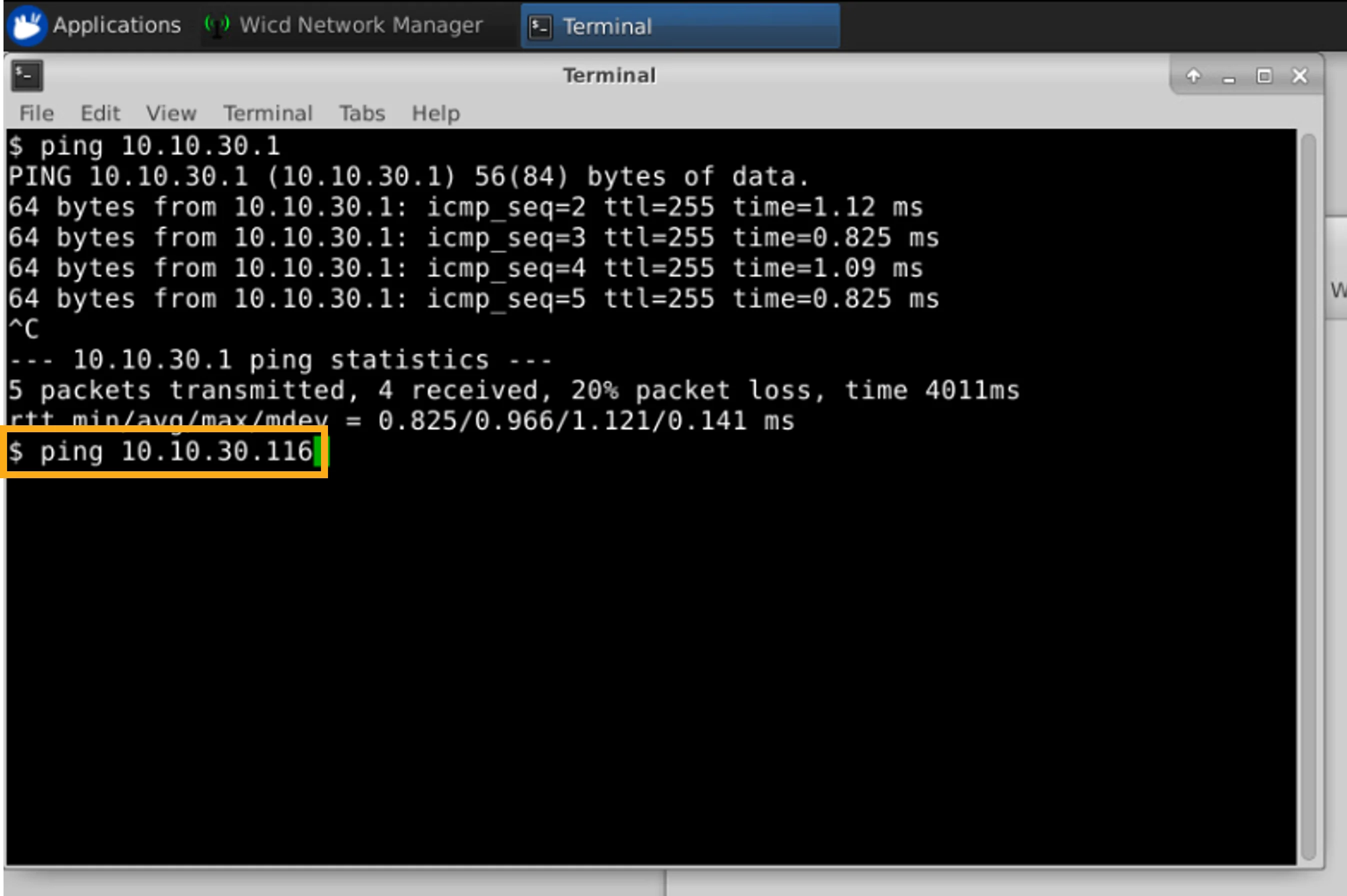
- Verify the result. All five pings were successful.驗證結果。全部五次 ping 都成功了。
Observe the Wireless Network Information on Client PC 2
在用戶端 PC 2 上觀察無線網路資訊
Now you will look at information about the wireless network to which Client PC 2 is connected.
現在你將檢視用戶端 PC 2 所連線之無線網路的相關資訊。
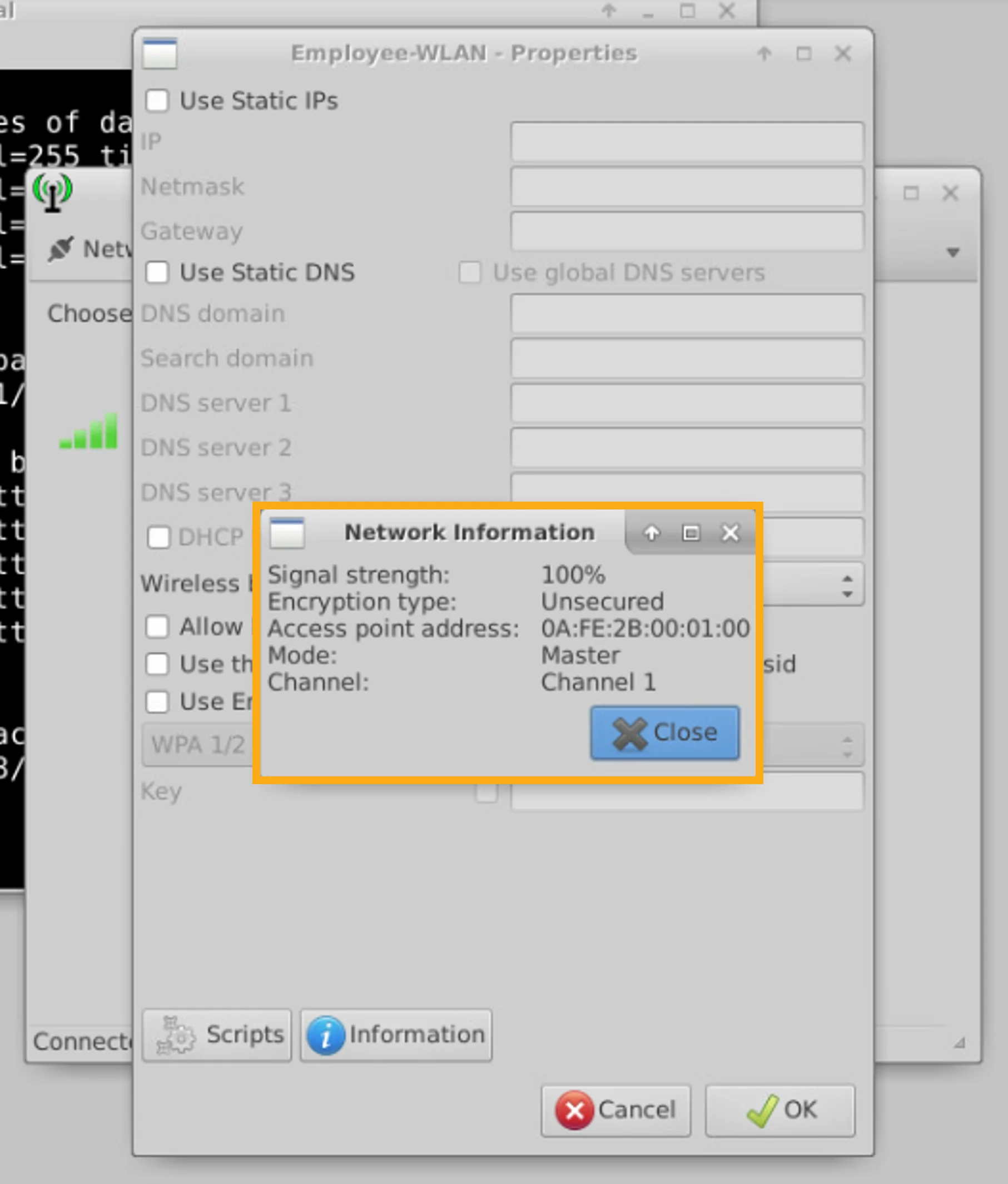
Use the Wicd Network Manager on Client PC 2 to observe information about the Employee-WLAN.
在用戶端 PC 2 上使用 Wicd Network Manager 觀察 Employee-WLAN 的相關資訊。
You will see that the WLAN is open (unsecured), that Client PC 2 is connected to the AP with MAC address 0A:FE:2B:00:01:00, and that the connection has been established on Channel 1.
你會看到該 WLAN 是開放式(未加密)的,用戶端 PC 2 連線到 MAC 位址為 0A:FE:2B:00:01:00 的 AP,且該連線已在頻道 1 上建立。
To display the network information, perform the following procedure:
請執行下列程序來顯示網路資訊:
- Click any visible part of the Wicd Network Manager window that is currently behind the terminal window to bring the application to the foreground.按一下目前位於終端機視窗後方的 Wicd Network Manager 視窗中任何可見的部分,將該應用程式帶到前景。
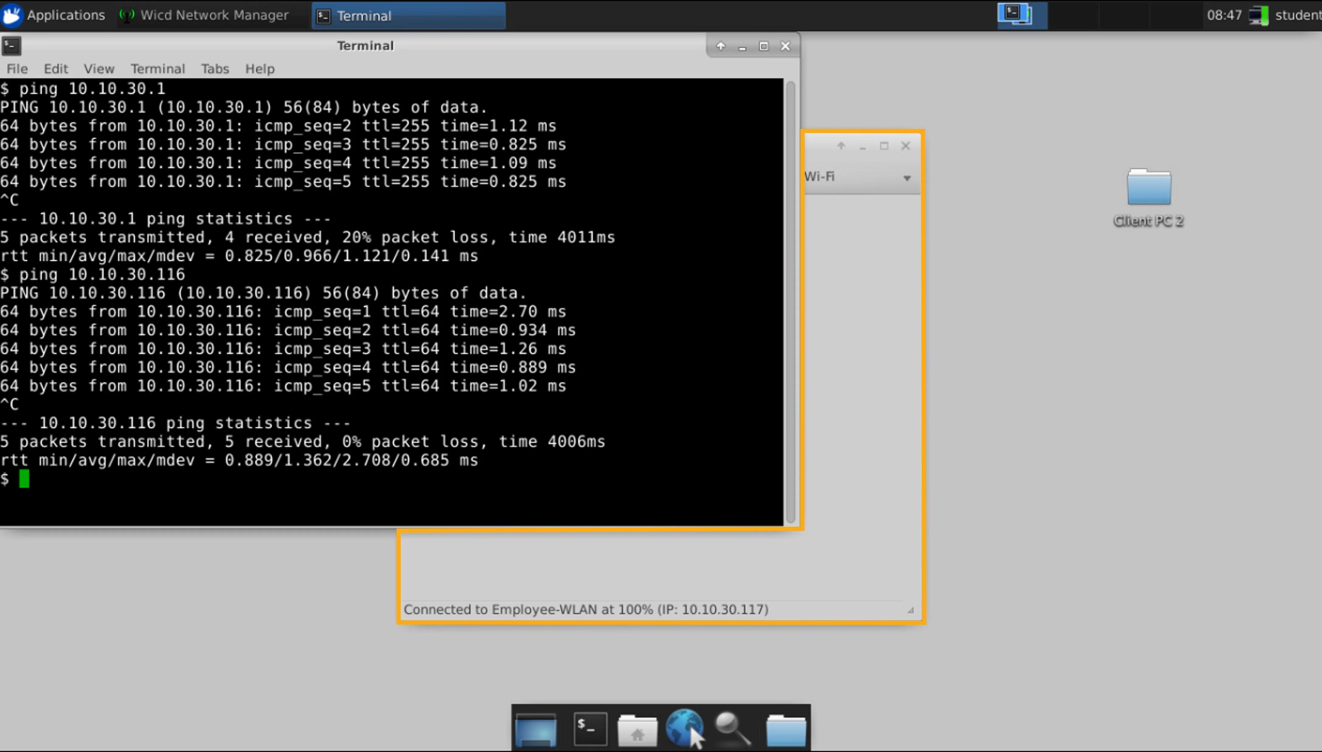
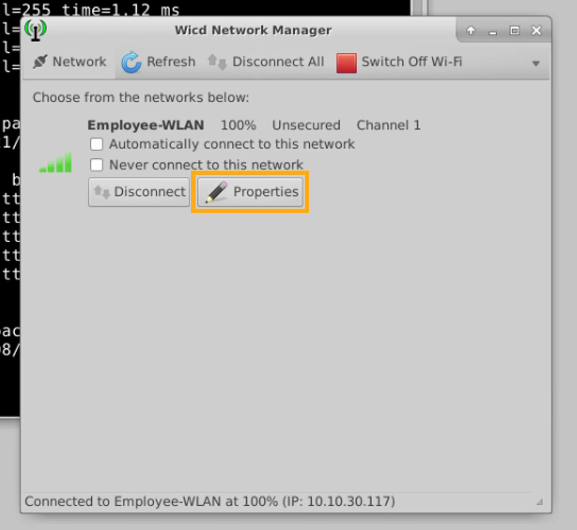
- In the Wicd Network Manager, click Properties.在 Wicd Network Manager 中,按一下 Properties。
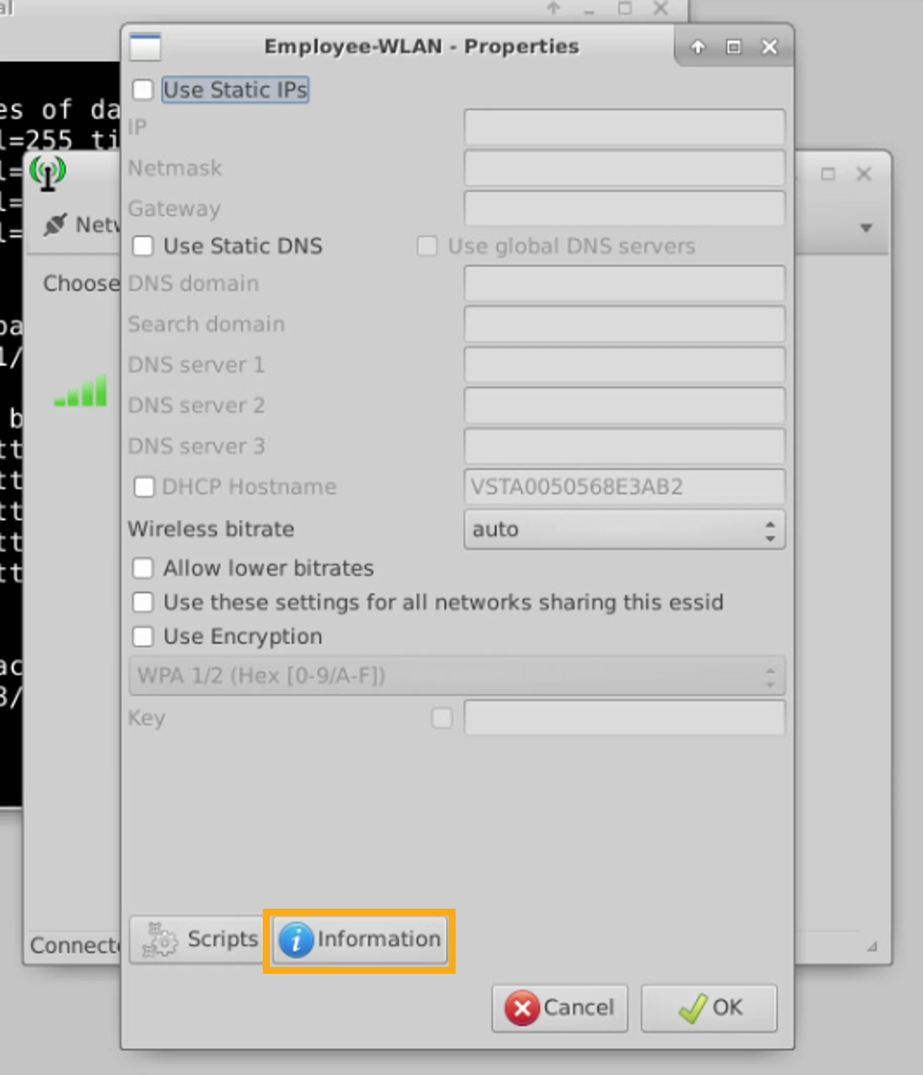
- In the Employee-WLAN " Properties window, click Information.在 Employee-WLAN " Properties 視窗中,按一下 Information。
- Examine the displayed network information.檢視顯示的網路資訊。
You can see that the WLAN is open (unsecured), that Client PC 2 is connected to the AP with MAC address 0A:FE:2B:00:01:00, and that the connection has been established on Channel 1.
你可以看到該 WLAN 是開放式(未加密)的,用戶端 PC 2 連線到 MAC 位址為 0A:FE:2B:00:01:00 的 AP,且該連線已在頻道 1 上建立。
Review the Wireless Status: Basic Page Information
檢視無線狀態:Basic 頁面資訊
Now you will switch back to the Admin PC to view the wireless network status on the Campus WLC.
現在你將切換回管理用 PC,以檢視 Campus WLC 上的無線網路狀態。
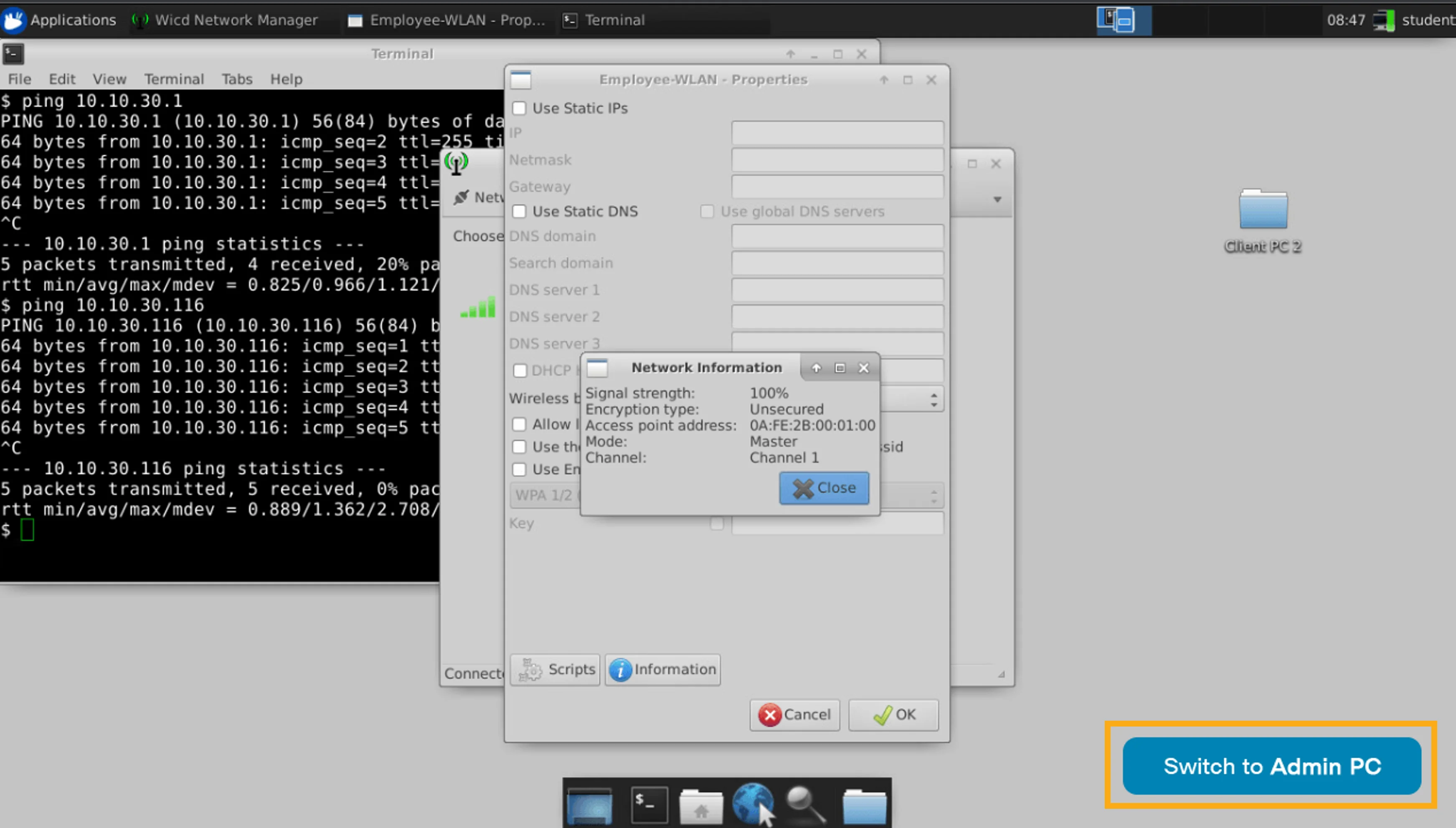
Click the Switch to Admin PC button, which is located at the bottom-right corner of the desktop to switch from Client PC 2 to the Admin PC.
按一下位於桌面右下角的 Switch to Admin PC 按鈕,從用戶端 PC 2 切換到管理用 PC。
You can see that the WLC web GUI Campus location indicates that it has no clients. Click the browser Reload icon to update the location information.
你可以看到 WLC 網頁 GUI 中 Campus 位置顯示沒有用戶端。按一下瀏覽器的 Reload 圖示以更新位置資訊。
After refreshing the page, verify that the location indicates two clients.
重新整理頁面後,驗證該位置是否顯示兩個用戶端。
View Client Details on the Campus WLC
檢視 Campus WLC 上的用戶端詳細資料
You will now examine more details about the wireless clients that are connected to the WLAN.
你現在將檢視有關已連線到該 WLAN 之無線用戶端的更多詳細資料。
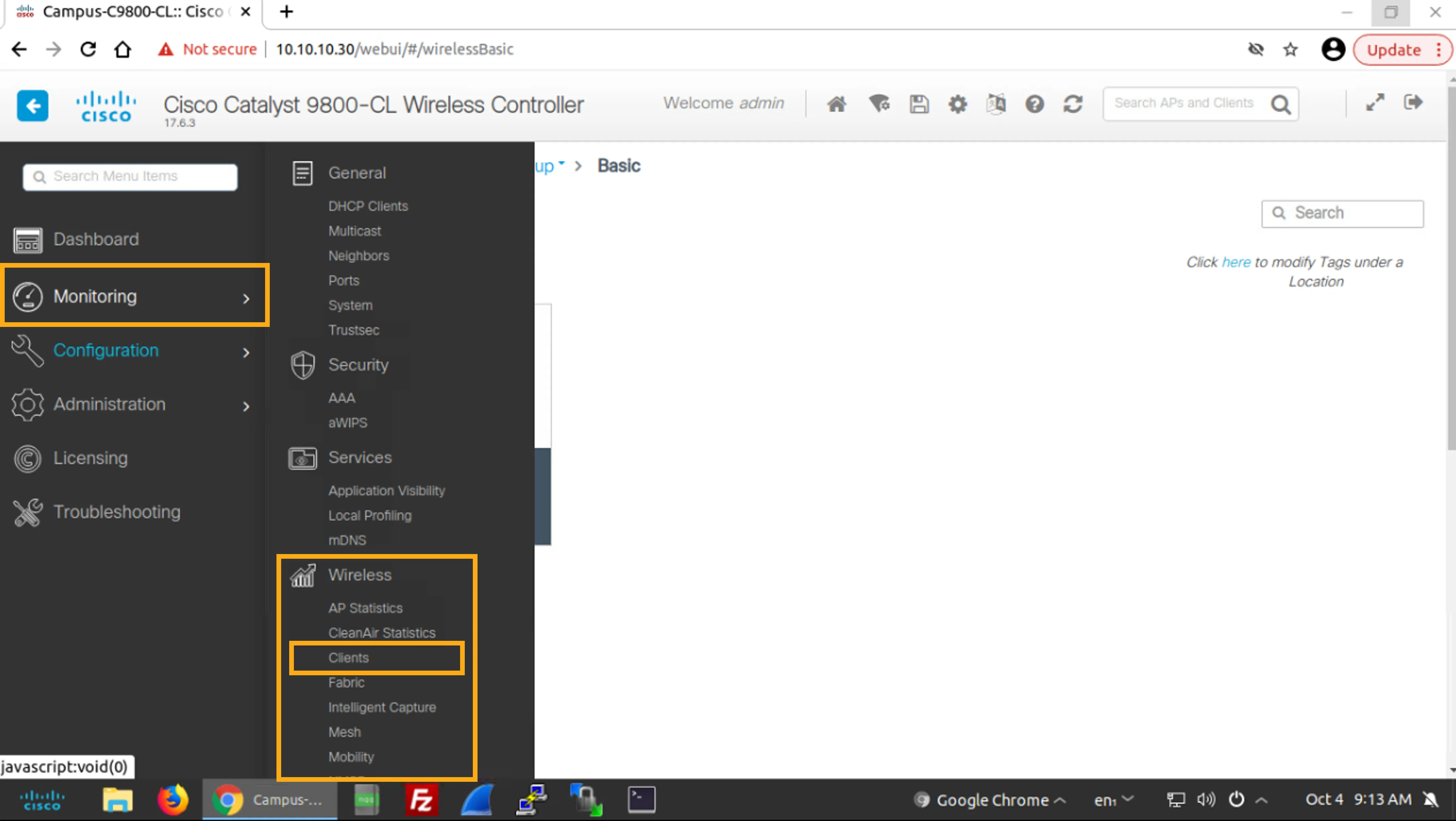
Choose Monitoring > Wireless > Clients.
選擇 Monitoring > Wireless > Clients。
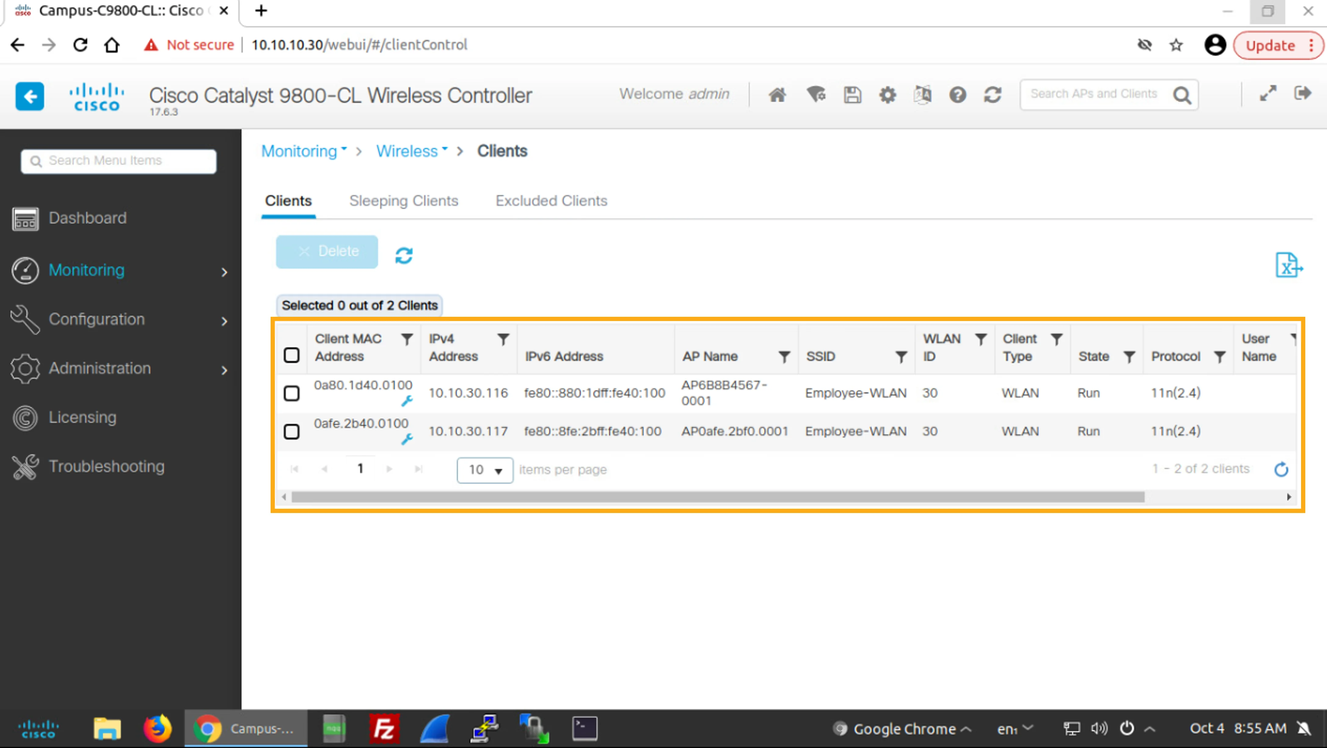
Verify that you can see the two connected WLAN clients, including their MAC address and client IP address.
驗證你可以看到兩個已連線的 WLAN 用戶端,包括它們的 MAC 位址與用戶端 IP 位址。
You can also see the name of the AP to which the clients are connected, their SSID, and the WLAN ID.
你也可以看到用戶端所連線 AP 的名稱、其 SSID,以及 WLAN ID。
Client Information
用戶端資訊
Let's see what information about the connected clients the WLC provides.
讓我們看看 WLC 提供了哪些已連線用戶端的資訊。
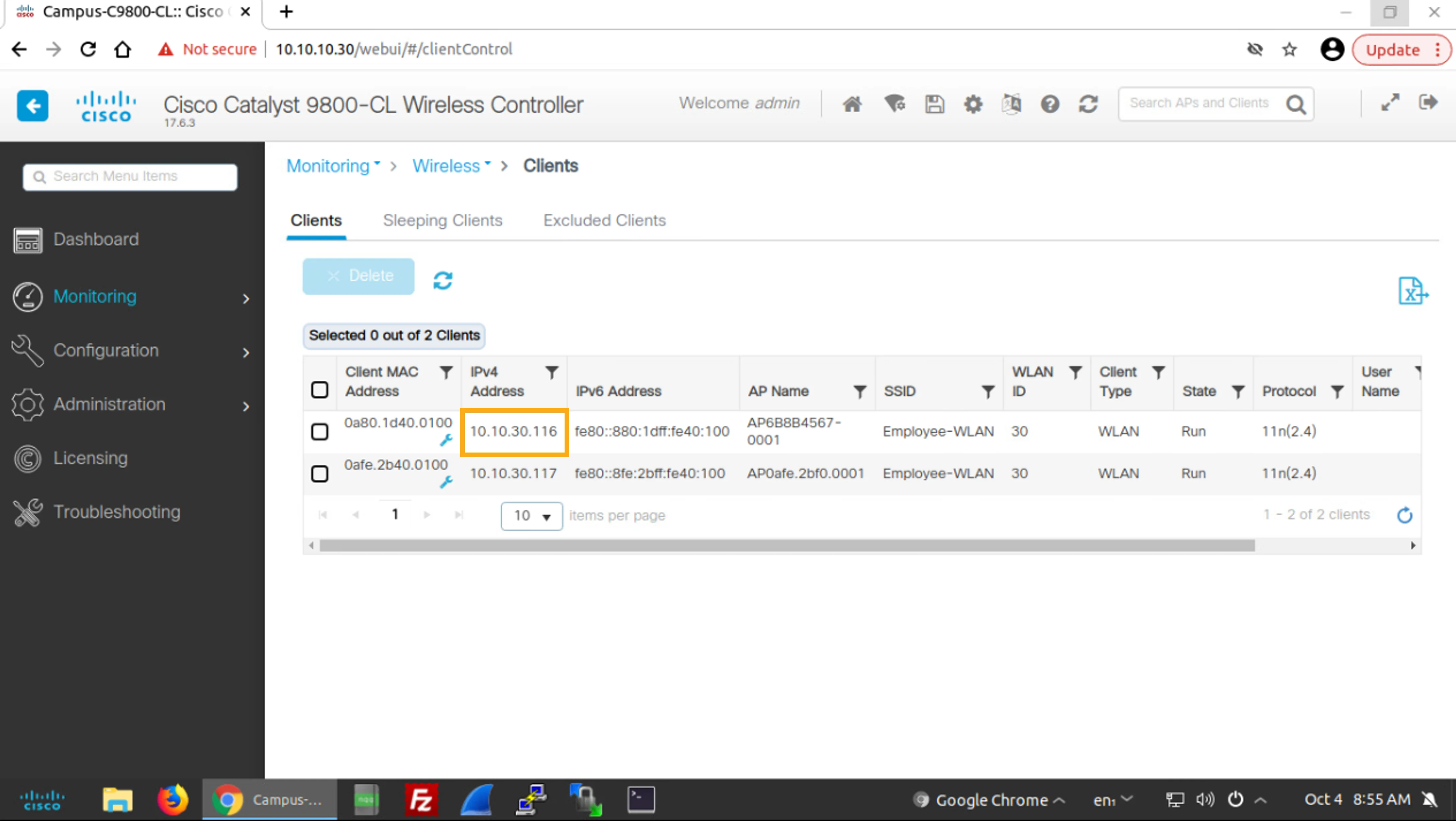
Click the IP address of the first client (10.10.30.116, the IP address of Client PC 1) to get to the 360 View of the client.
按一下第一個用戶端(10.10.30.116,也就是用戶端 PC 1 的 IP 位址)的 IP 位址,進入該用戶端的 360 View。
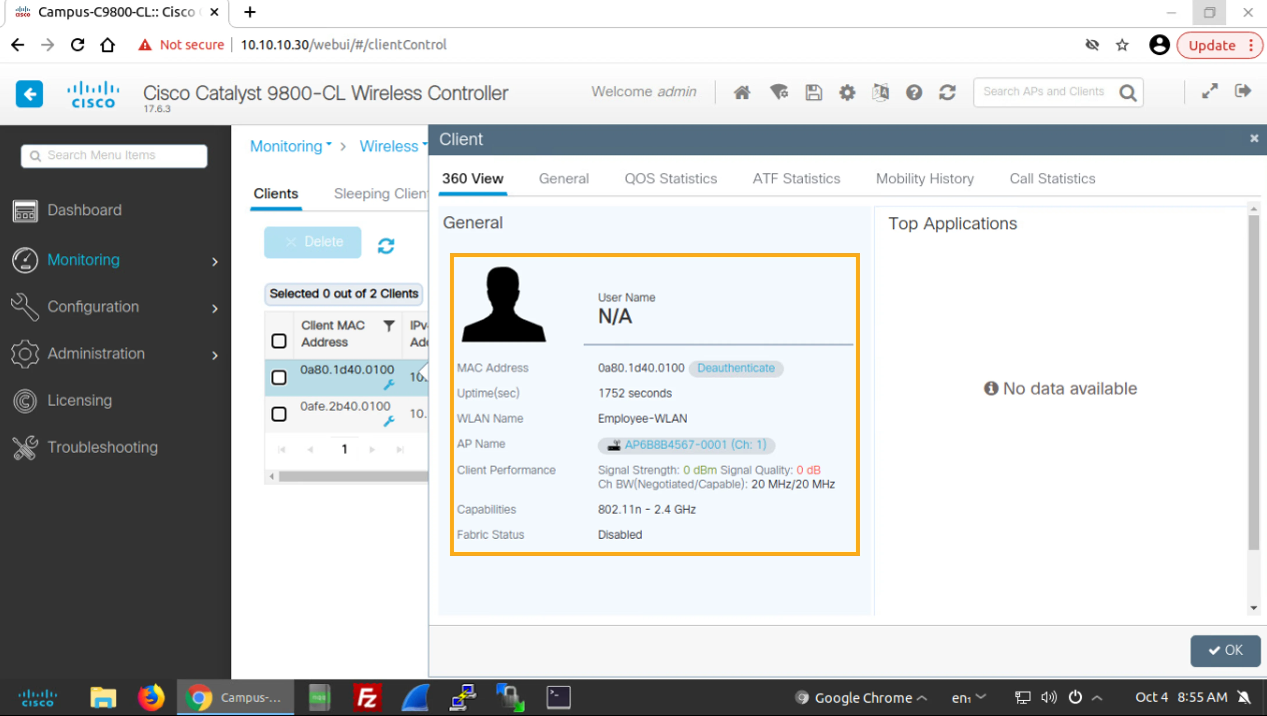
Examine the displayed information.
檢視顯示的資訊。
You can see User Name, client MAC Address, Uptime, WLAN Name, AP Name, client Capabilities, and more.
你可以看到 User Name、用戶端 MAC Address、Uptime、WLAN Name、AP Name、用戶端 Capabilities 等資訊。
The Client Properties tab of the General tab provides even more client information. Review the displayed information.
General 標籤頁中的 Client Properties 標籤頁提供了更多用戶端資訊。請檢視顯示的資訊。
Click the General tab.
按一下 General 標籤頁。
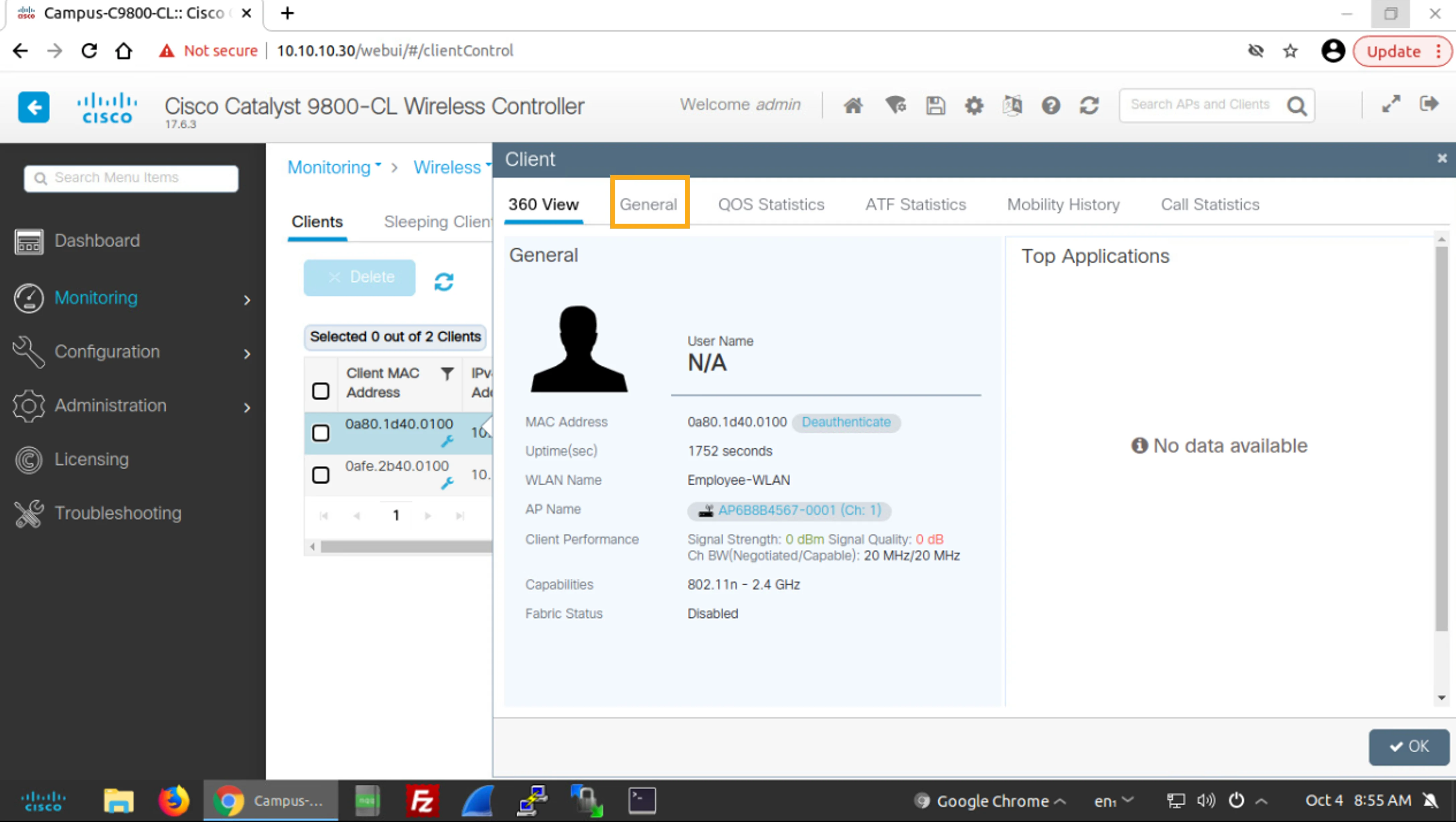
You will see the client information that is available in the Client Properties tab.
你會看到 Client Properties 標籤頁中提供的用戶端資訊。
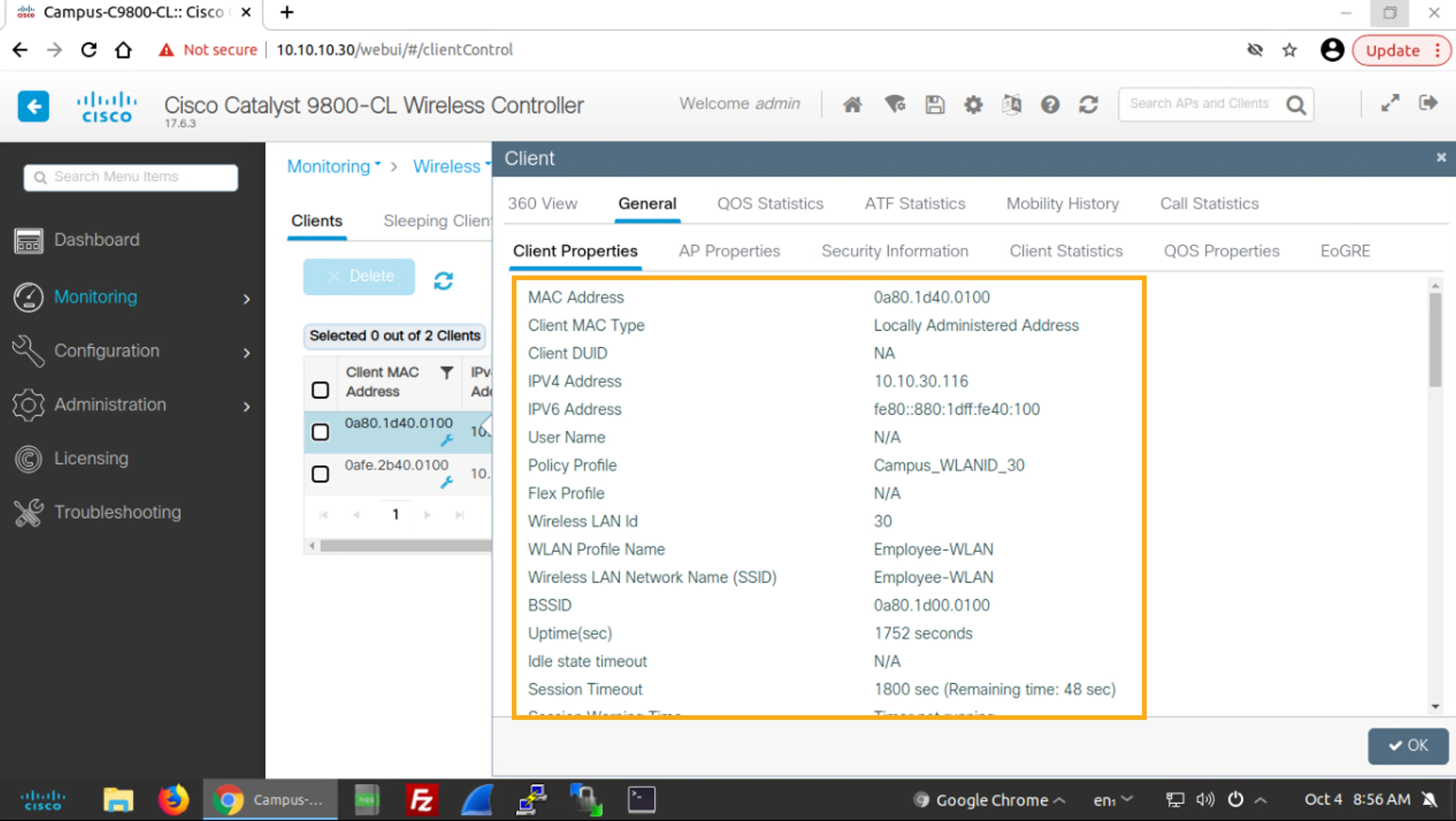
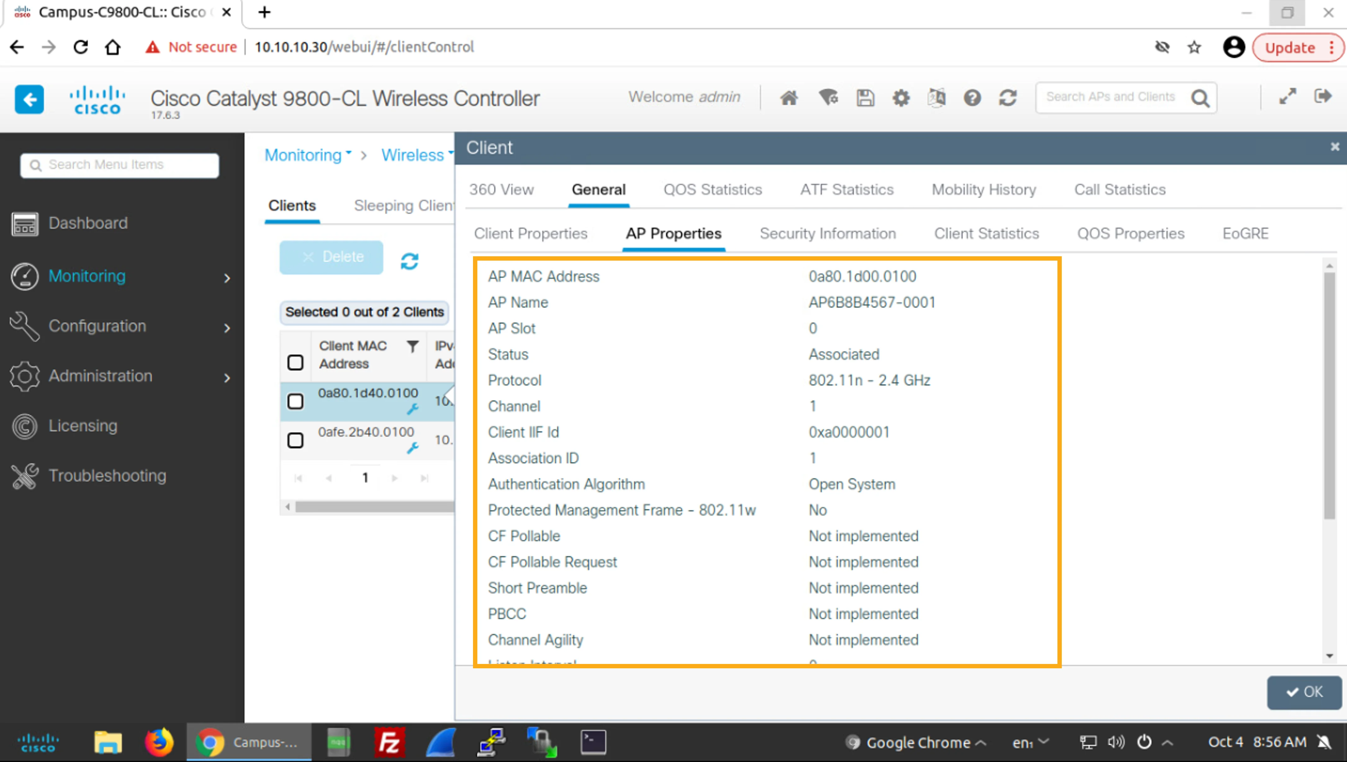
The AP Properties tab goes into the AP details. Review the information about the AP, to which the client is connected.
AP Properties 標籤頁會深入呈現 AP 的詳細資料。請檢視用戶端所連線 AP 的相關資訊。
Click the AP Properties tab.
按一下 AP Properties 標籤頁。
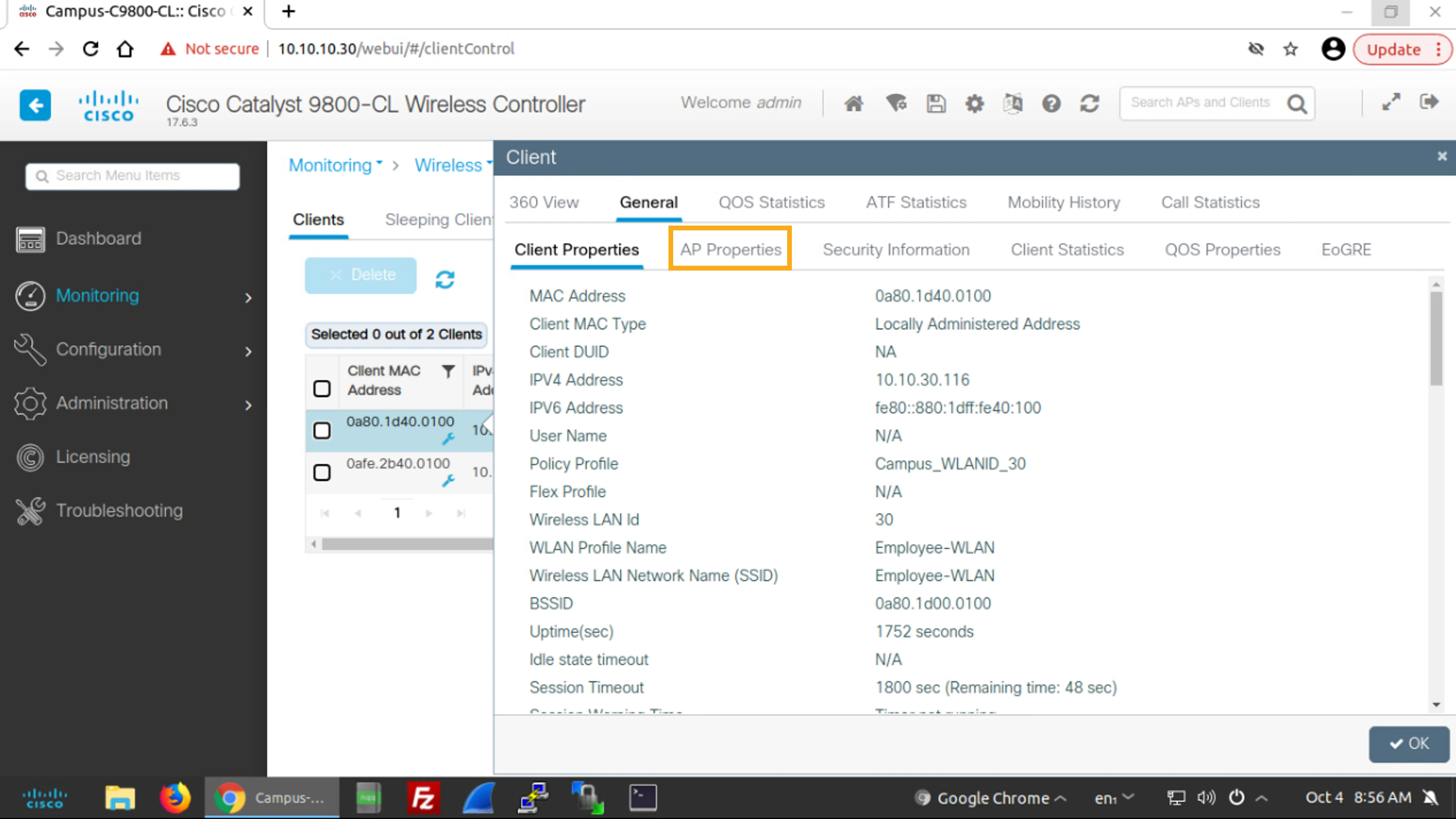
You will see the client information that is available in the AP Properties tab.
你會看到 AP Properties 標籤頁中提供的用戶端資訊。
AP Statistics
AP 統計資料
Now, let's look at the AP statistics.
現在,讓我們看看 AP 統計資料。
Return to the 360 View tab and click the name that the AP Name field displays, which is the AP, to which the client is connected.
回到 360 View 標籤頁,並按一下 AP Name 欄位顯示的名稱,也就是用戶端所連線的那個 AP。
Click the 360 View tab.
按一下 360 View 標籤頁。
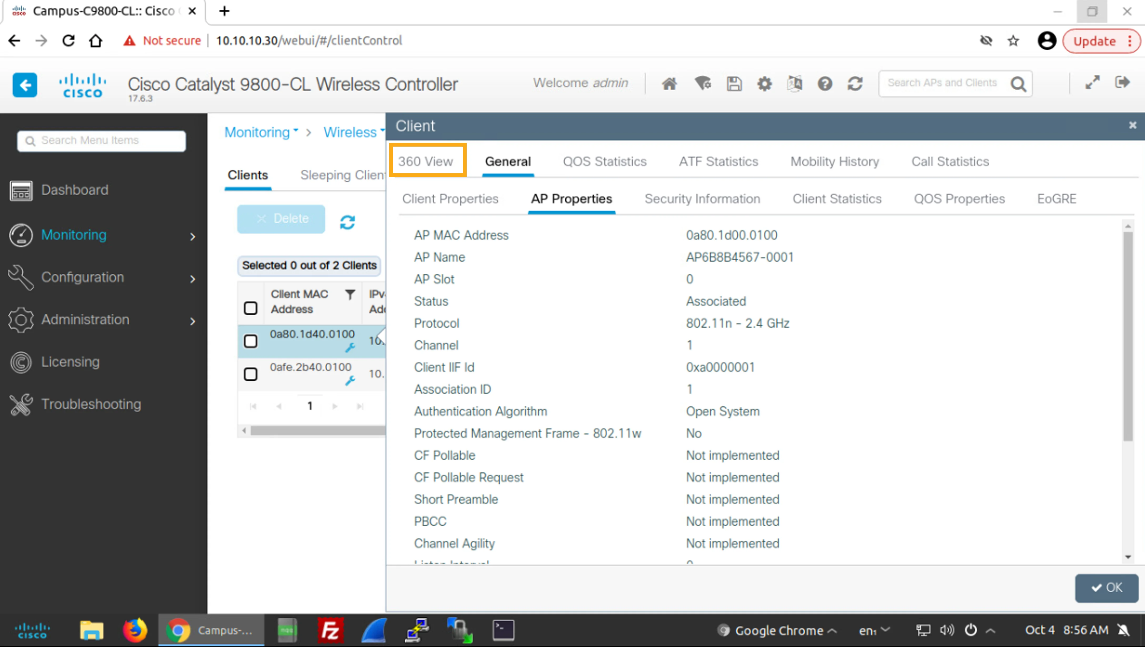
Click the name of the AP, AP6B8B4567-0001 (Ch: 1).
按一下該 AP 的名稱 AP6B8B4567-0001 (Ch: 1)。
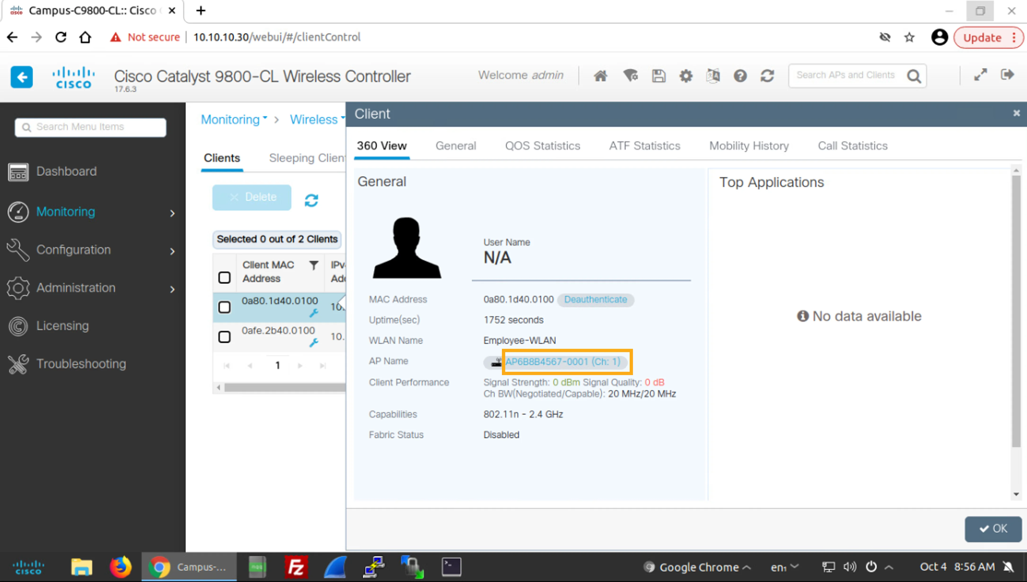
You are taken to the Monitor > Wireless > AP Statistics page. A filter for the AP Name is active. As a result, you only see the AP that you clicked at the 360 View of the client.
系統會將你帶到 Monitor > Wireless > AP Statistics 頁面。AP Name 的篩選器目前啟用中。因此,你只會看到你在用戶端 360 View 中所按一下的那個 AP。
Observe the information that is provided in this filtered AP list. It includes the AP Name, AP Model, Admin Status, IP Address, and AP Radio MAC.
觀察此已篩選的 AP 清單中提供的資訊,其中包括 AP Name、AP Model、Admin Status、IP Address 以及 AP Radio MAC。
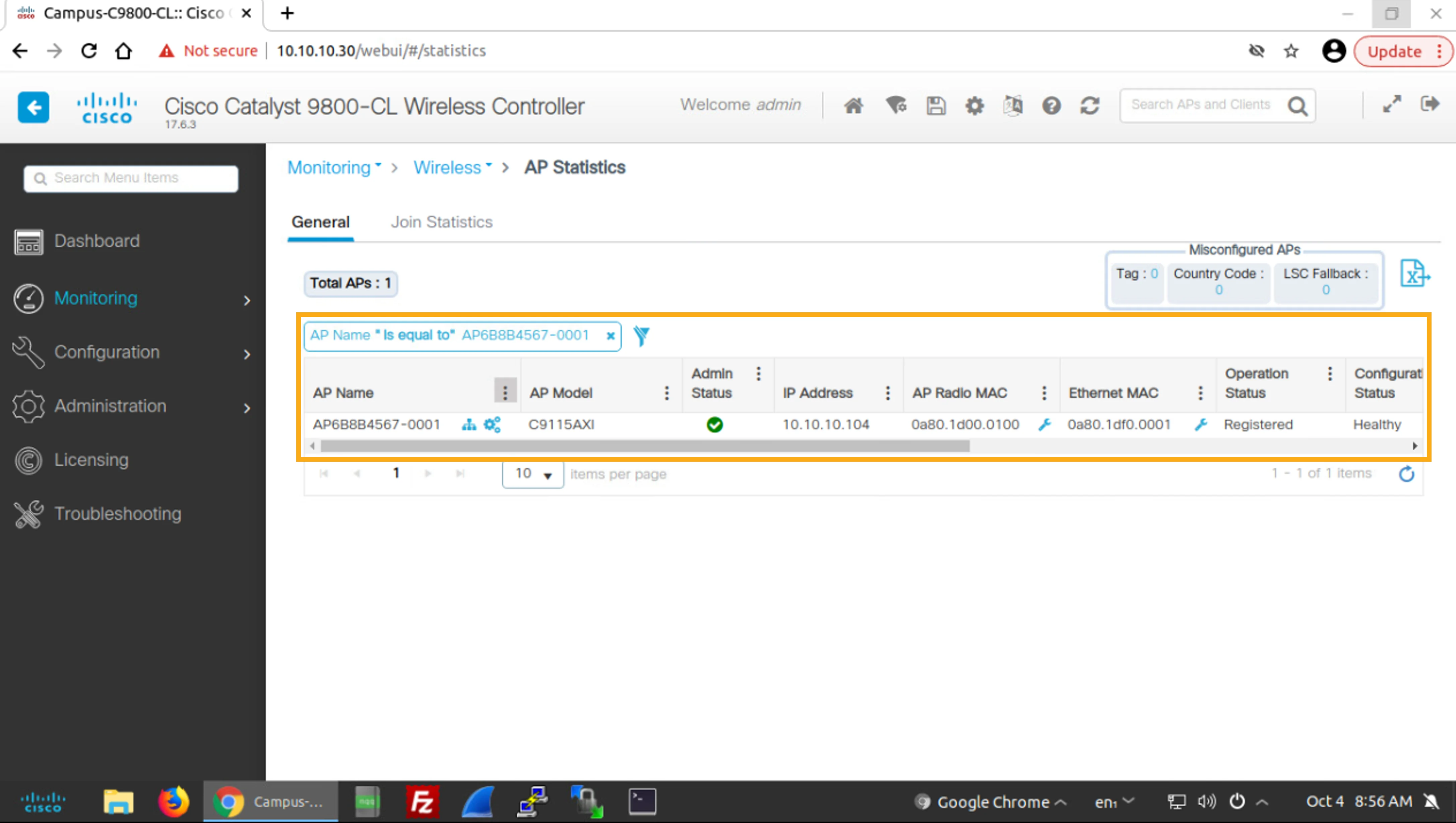
Click the AP AP6B8B4567-0001 to get to the 360 View of the AP.
按一下 AP AP6B8B4567-0001,進入該 AP 的 360 View。
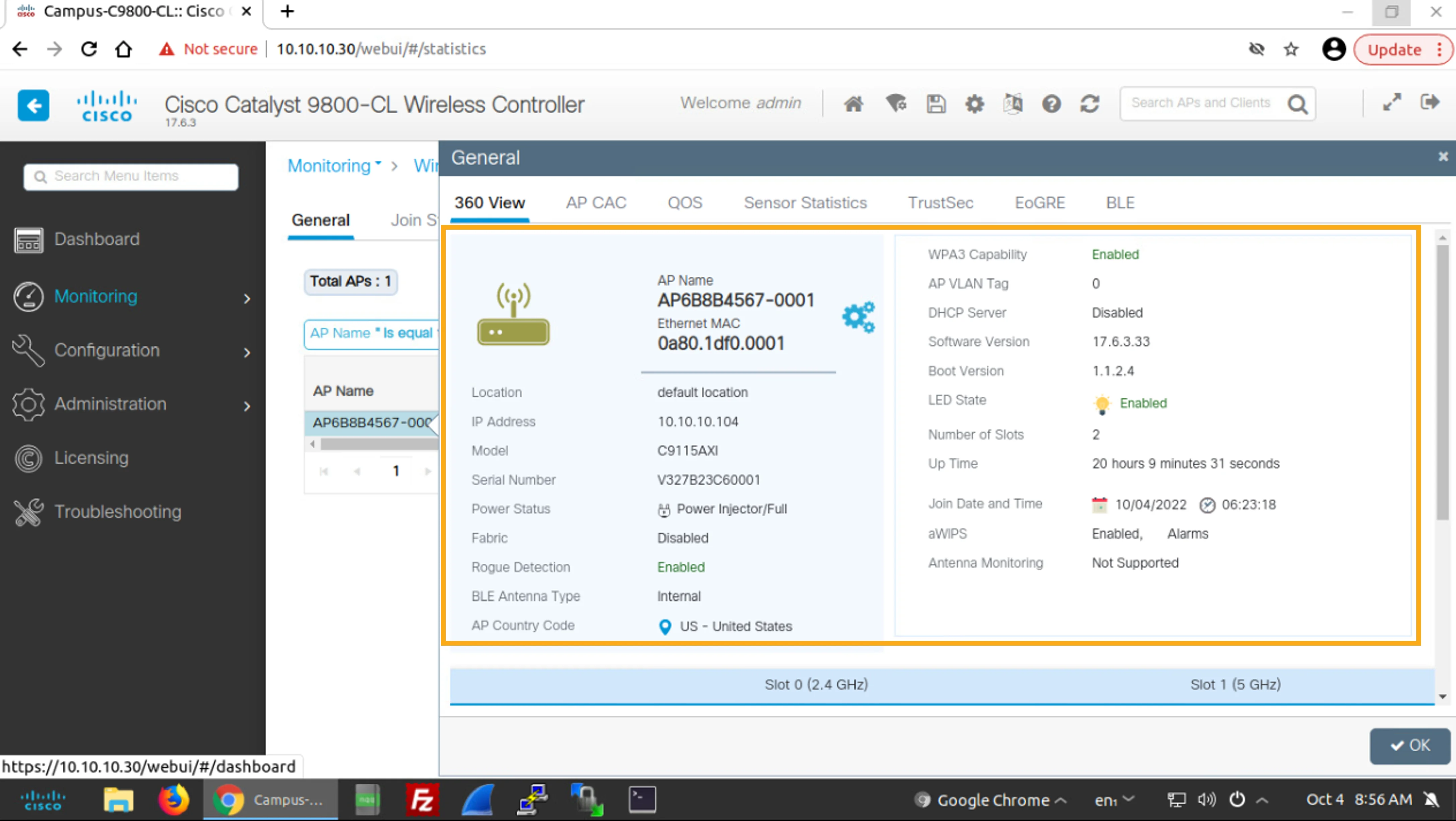
Examine the information that is provided in the 360 View of the AP. It displays additional information about the AP, including its Serial Number, Power Status, BLE Antenna Type, configuration settings such as Rogue Detection, DHCP Server status, Software Version, and Boot Version.
檢視 AP 的 360 View 中提供的資訊。其中顯示了該 AP 的其他資訊,包括其 Serial Number、Power Status、BLE Antenna Type,以及設定選項如 Rogue Detection、DHCP Server 狀態、Software Version 與 Boot Version。
Dashboard
儀表板
Finally, let's return to the Campus WLC Dashboard.
最後,讓我們回到 Campus WLC 的 Dashboard。
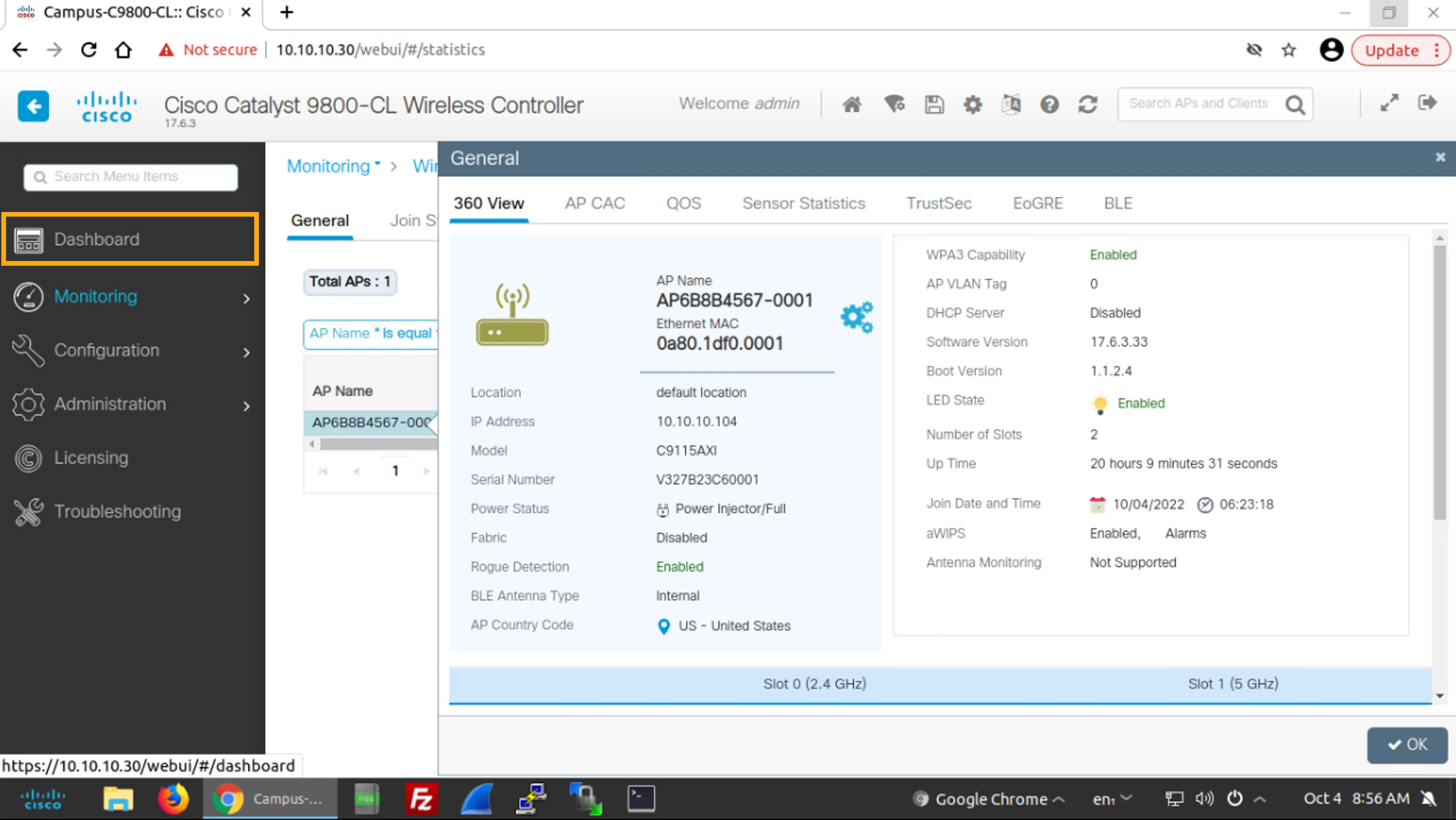
Choose Dashboard to examine the current WLAN status.
選擇 Dashboard 以檢視目前的 WLAN 狀態。
Choose Dashboard.
選擇 Dashboard。
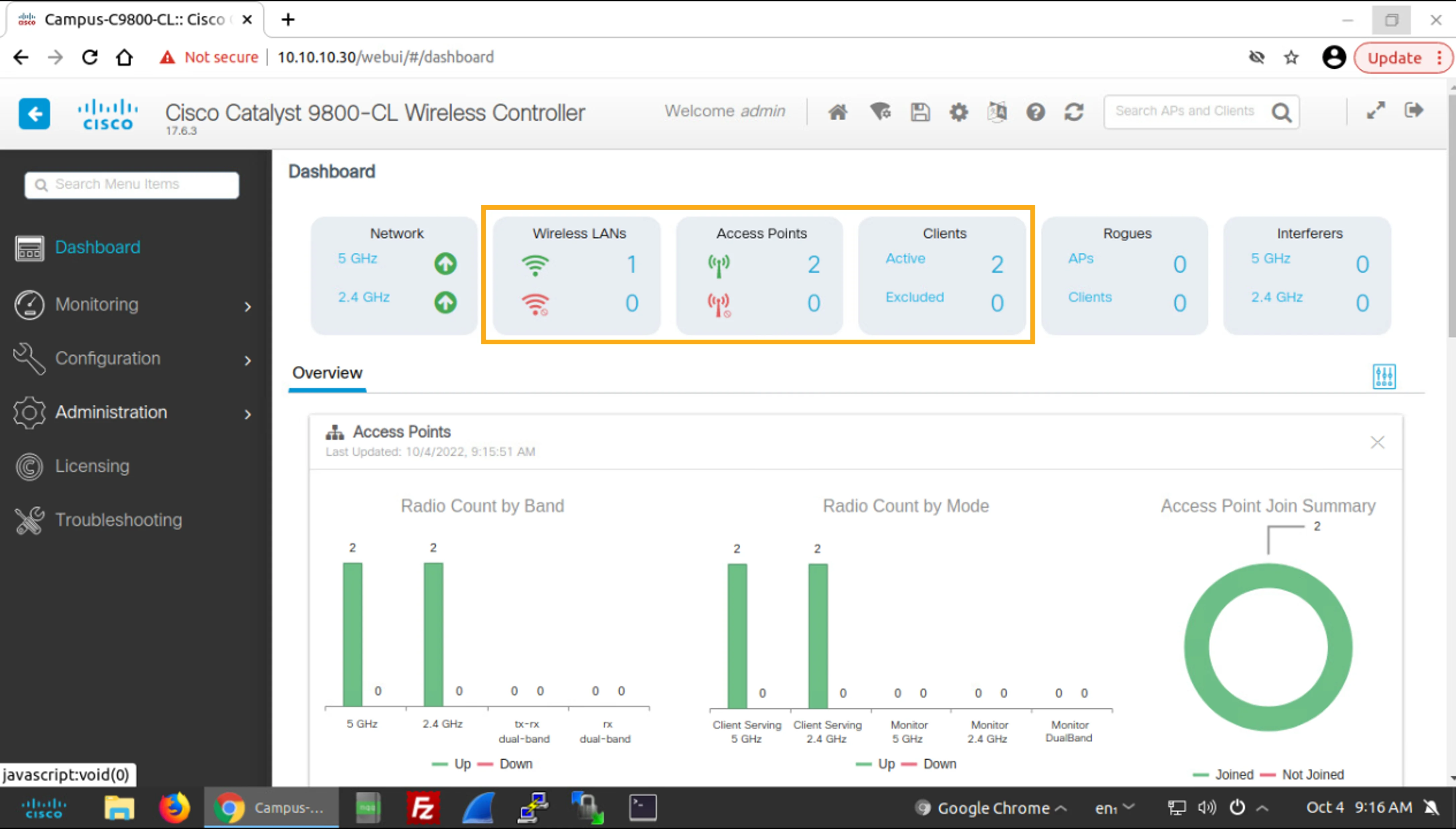
You can see that that the number of WLANs, APs, and Clients reflect the correct current situation in the wireless network.
你可以看到 WLAN、AP 與用戶端的數量正確反映出無線網路目前的實際狀況。
You have reached the last step of this simulation. Click Exit Lab Mode to end the simulation.
你已完成本模擬的最後一個步驟。按一下 Exit Lab Mode 結束模擬。