Introduction
簡介
In this activity, you will first implement dynamic NAT to verify the dynamic translation process. Then you will change dynamic NAT to PAT so that all devices in the internal network can access outside resources using only one public IPv4 address.
在本活動中,你將先實作動態 NAT,以驗證動態轉譯程序。接著你會將動態 NAT 改為 PAT,讓內部網路中所有裝置只用一個公用 IPv4 位址即可存取外部資源。
Topology
拓樸
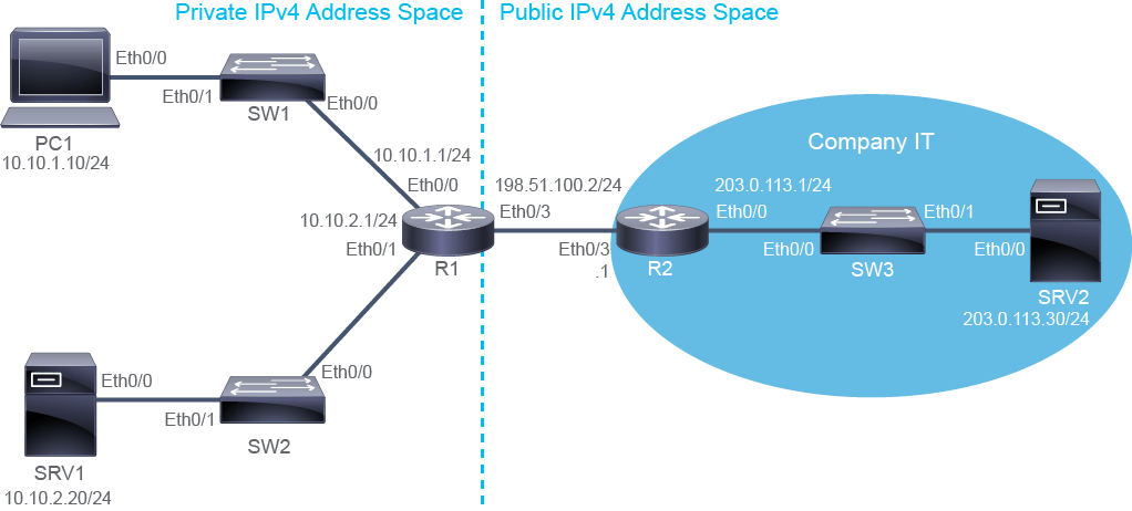
Job Aid
工作輔助資料
Device Information
裝置資訊
Device Information Table
裝置資訊表
Device 裝置 | Characteristic 特性 | Value 數值 |
PC1 PC1 | IPv4 address IPv4 位址 | 10.10.1.10/24 10.10.1.10/24 |
PC1 PC1 | Default gateway 預設閘道 | 10.10.1.1 10.10.1.1 |
SRV1 SRV1 | IPv4 address IPv4 位址 | 10.10.2.20/24 10.10.2.20/24 |
SRV1 SRV1 | Default gateway 預設閘道 | 10.10.2.1 10.10.2.1 |
SRV2 SRV2 | IPv4 address IPv4 位址 | 203.0.113.30/24 203.0.113.30/24 |
SRV2 SRV2 | Default gateway 預設閘道 | 203.0.113.1 203.0.113.1 |
SRV2 SRV2 | Credentials 認證資訊 | admin / Cisco123 admin / Cisco123 |
SW1 SW1 | VLAN 1 IPv4 address VLAN 1 IPv4 位址 | 10.10.1.4/24 10.10.1.4/24 |
SW1 SW1 | Default gateway 預設閘道 | 10.10.1.1 10.10.1.1 |
SW1 SW1 | Ethernet0/0 description Ethernet0/0 描述 | Link to R1 連接至 R1 |
SW1 SW1 | Ethernet0/1 description Ethernet0/1 描述 | Link to PC1 連接至 PC1 |
SW2 SW2 | VLAN 1 IPv4 address VLAN 1 IPv4 位址 | 10.10.2.4/24 10.10.2.4/24 |
SW2 SW2 | Default gateway 預設閘道 | 10.10.2.1 10.10.2.1 |
SW2 SW2 | Ethernet0/0 description Ethernet0/0 描述 | Link to R1 連接至 R1 |
SW2 SW2 | Ethernet0/1 description Ethernet0/1 描述 | Link to SRV1 連接至 SRV1 |
SW3 SW3 | VLAN 1 IPv4 address VLAN 1 IPv4 位址 | 203.0.113.4/24 203.0.113.4/24 |
SW3 SW3 | Default gateway 預設閘道 | 203.0.113.1 203.0.113.1 |
SW3 SW3 | Ethernet0/0 description Ethernet0/0 描述 | Link to R2 連接至 R2 |
SW3 SW3 | Ethernet0/1 description Ethernet0/1 描述 | Link to SRV2 連接至 SRV2 |
R1 R1 | Ethernet0/0 description Ethernet0/0 描述 | Link to SW1 連接至 SW1 |
R1 R1 | Ethernet0/0 IPv4 address Ethernet0/0 IPv4 位址 | 10.10.1.1/24 10.10.1.1/24 |
R1 R1 | Ethernet0/1 description Ethernet0/1 描述 | Link to SW2 連接至 SW2 |
R1 R1 | Ethernet0/1 IPv4 address Ethernet0/1 IPv4 位址 | 10.10.2.1/24 10.10.2.1/24 |
R1 R1 | Ethernet0/3 description Ethernet0/3 描述 | Link to R2 連接至 R2 |
R1 R1 | Ethernet0/3 IPv4 address Ethernet0/3 IPv4 位址 | 198.51.100.2/24 198.51.100.2/24 |
R2 R2 | Ethernet0/0 description Ethernet0/0 描述 | Link to SW3 連接至 SW3 |
R2 R2 | Ethernet0/0 IPv4 address Ethernet0/0 IPv4 位址 | 203.0.113.1/24 203.0.113.1/24 |
R2 R2 | Ethernet0/3 description Ethernet0/3 描述 | Link to R1 連接至 R1 |
R2 R2 | Ethernet0/3 IPv4 address Ethernet0/3 IPv4 位址 | 198.51.100.1/24 198.51.100.1/24 |
Global IPv4 Address Networks
全域 IPv4 位址網路
Address Block 位址區塊 | Host Starting Address 起始主機位址 | Host Ending Address 結束主機位址 | Broadcast Address 廣播位址 | Subnet Mask 子網路遮罩 |
192.0.2.0/24 192.0.2.0/24 | 192.0.2.1 192.0.2.1 | 192.0.2.254 192.0.2.254 | 192.0.2.255 192.0.2.255 | 255.255.255.0 255.255.255.0 |
198.51.100.0/24 198.51.100.0/24 | 198.51.100.1 198.51.100.1 | 198.51.100.254 198.51.100.254 | 198.51.100.255 198.51.100.255 | 255.255.255.0 255.255.255.0 |
203.0.113.0/24 203.0.113.0/24 | 203.0.113.1 203.0.113.1 | 203.0.113.254 203.0.113.254 | 203.0.113.255 203.0.113.255 | 255.255.255.0 255.255.255.0 |
Task 1: Configure Dynamic NAT
任務 1:設定動態 NAT
Activity
活動
Static NAT is currently configured on R1 to provide a static public address for SRV1. SRV1 has internet connectivity, both outbound and inbound. However, devices in the 10.10.1.0/24 subnet and other devices in the 10.10.2.0/24 subnet cannot access the outside networks. Access the console of PC1 and SW2 and verify that they have no connectivity to SRV2.
R1 目前已設定靜態 NAT,為 SRV1 提供靜態公用位址。SRV1 具有出向與入向的網際網路連線能力。然而,10.10.1.0/24 子網路中的裝置以及 10.10.2.0/24 子網路中的其他裝置卻無法存取外部網路。存取 PC1 與 SW2 的主控台,驗證它們無法連線至 SRV2。
On PC1, enter the following command:
在 PC1 上,輸入以下指令:
PC1# ping 203.0.113.30
Type escape sequence to abort.
Sending 5, 100-byte ICMP Echos to 203.0.113.30, timeout is 2 seconds:
.....
Success rate is 0 percent (0/5)
On SW2, enter the following command:
在 SW2 上,輸入以下指令:
SW2# ping 203.0.113.30
Type escape sequence to abort.
Sending 5, 100-byte ICMP Echos to 203.0.113.30, timeout is 2 seconds:
.....
Success rate is 0 percent (0/5)
The connectivity tests fail. The reason is not that the ECHO requests sent from PC1 and SW2 do not reach SRV2. SRV2 receives the ECHO requests and sends the ECHO replies to addresses of PC1 and SW2. Both of these addresses belong to the private IPv4 address range. When the replies reach R2, it will discard them. R2 does not have routes in its routing table, which it can use to forward traffic towards private IPv4 subnets.
連線測試失敗。原因並非 PC1 與 SW2 送出的 ECHO 請求未能到達 SRV2。SRV2 收到 ECHO 請求後,會將 ECHO 回應送往 PC1 與 SW2 的位址。這兩個位址都屬於私有 IPv4 位址範圍。當回應到達 R2 時,R2 會將其丟棄,因為 R2 的路由表中沒有可用來將流量轉發至私有 IPv4 子網路的路由。
R1 interfaces Ethernet0/1 and Ethernet0/3 are configured for NAT. Verify the configuration using the show ip nat statistics command.
R1 的 Ethernet0/1 與 Ethernet0/3 介面已設定為 NAT。使用 show ip nat statistics 指令驗證設定。
On R1, enter the following command:
在 R1 上,輸入以下指令:
R1# show ip nat statistics
Total active translations: 1 (1 static, 0 dynamic; 0 extended)
Peak translations: 1, occurred 00:10:40 ago
Outside interfaces:
 Ethernet0/3
Inside interfaces:
 Ethernet0/1
Hits: 0  Misses: 0
CEF Translated packets: 0, CEF Punted packets: 0
Expired translations: 0
Dynamic mappings:

Total doors: 0
Appl doors: 0
Normal doors: 0
Queued Packets: 0
The output confirms that Ethernet0/1 is configured as a NAT inside interface, Ethernet0/3 is configured as NAT outside interface, and that 1 static translation is configured.
輸出確認 Ethernet0/1 已設為 NAT 內部介面,Ethernet0/3 已設為 NAT 外部介面,且已設定 1 筆靜態轉譯。
Configure the Ethernet0/0 interface of the R1 router for NAT, and go to the global configuration mode.
Note: There will be a significant pause in response to the first interface NAT command because R1 will have to initiate an internal NVI to support NAT.
將 R1 路由器的 Ethernet0/0 介面設定為 NAT,並進入全域設定模式。
注意:第一個介面 NAT 指令的回應會有明顯延遲,因為 R1 必須先建立內部 NVI 以支援 NAT。
On R1, enter the following command:
在 R1 上,輸入以下指令:
R1# configure terminal
R1(config)# interface Ethernet0/0
R1(config-if)# ip nat insideR1(config-if)# exitOn R1, configure access list number 10 to identify which addresses should be translated. Define all addresses of the 10.10.0.0/16 subnet as NAT-eligible.
在 R1 上,設定編號 10 的存取清單,以識別哪些位址應被轉譯。將 10.10.0.0/16 子網路的所有位址定義為 NAT 適用位址。
On R1, enter the following command:
在 R1 上,輸入以下指令:
R1(config)# access-list 10 permit 10.10.0.0 0.0.255.255On R1, define a pool of global addresses named NAT_POOL that includes all address in the range from 198.51.100.100/24 to 198.51.100.149/24.
在 R1 上,定義一個名為 NAT_POOL 的全域位址集區,其中包含從 198.51.100.100/24 到 198.51.100.149/24 範圍內的所有位址。
On R1, enter the following command:
在 R1 上,輸入以下指令:
R1(config)# ip nat pool NAT_POOL 198.51.100.100 198.51.100.149 netmask 255.255.255.0 Define dynamic NAT by specifying the addresses that are identified in access list 10 as local addresses, and the addresses that are identified in the NAT_POOL pool as global addresses. Leave the global configuration mode.
將存取清單 10 中識別出的位址指定為本地位址,將 NAT_POOL 集區中識別出的位址指定為全域位址,藉此定義動態 NAT。接著離開全域設定模式。
On R1, enter the following commands:
在 R1 上,輸入以下指令:
R1(config)# ip nat inside source list 10 pool NAT_POOL
R1(config)# end
R1#Verify the bidirectional connectivity is now established between PC1 and SRV2 and between SW2 and SRV2.
驗證 PC1 與 SRV2 之間、以及 SW2 與 SRV2 之間現已建立雙向連線。
On PC1 and SW2, enter the following command:
在 PC1 與 SW2 上,輸入以下指令:
PC1# ping 203.0.113.30
Type escape sequence to abort.
Sending 5, 100-byte ICMP Echos to 203.0.113.30, timeout is 2 seconds:
!!!!!
Success rate is 100 percent (5/5), round-trip min/avg/max = 1/1/1 ms

SW2# ping 203.0.113.30
Type escape sequence to abort.
Sending 5, 100-byte ICMP Echos to 203.0.113.30, timeout is 2 seconds:
!!!!!
Success rate is 100 percent (5/5), round-trip min/avg/max = 1/1/1 ms
Both pings are successful.
兩個 ping 都成功。
Access the console of R1 to verify that connectivity is restored, thanks to the NAT configuration. On R1, view the current translation table.
存取 R1 的主控台,驗證連線已因 NAT 設定而恢復。在 R1 上檢視目前的轉譯表。
On R1, enter the following command:
在 R1 上,輸入以下指令:
R1# show ip nat translations
Pro Inside global      Inside local       Outside local      Outside global
icmp 198.51.100.100:1  10.10.1.10:1       203.0.113.30:1     203.0.113.30:1
--- 198.51.100.100 10.10.1.10         ---                ---
icmp 198.51.100.101:1  10.10.2.4:1        203.0.113.30:1     203.0.113.30:1
--- 198.51.100.101 10.10.2.4          ---                ---
--- 198.51.100.20      10.10.2.20         ---                ---
There is a total of five translation entries in the table, two extended and three simple entries.
表中共有五筆轉譯項目,其中兩筆為延伸項目,三筆為簡單項目。
The two extended entries that are associated with the ICMP traffic are short-lived and may have timed out. If they did, you can resend the ping from PC1 and SW2, and display the translation table again.
與 ICMP 流量相關的兩筆延伸項目存續時間短,可能已逾時。若已逾時,你可以從 PC1 與 SW2 重新送出 ping,再次顯示轉譯表。
There are three simple entries in the table. The simple entry mapping 10.10.2.20 to 198.51.100.20 is associated with the static NAT configuration. The remaining two simple entries are associated with the dynamic assignment of two addresses from the NAT_POOL pool, one for the translation of PC1 IPv4 address and the other for the translation of SW2 IPv4 address. PC1 was the first to generate traffic and it was assigned the first IPv4 address available in NAT_POOL (198.51.100.100). The next available IPv4 address from NAT_POOL, 198.51.100.101, was assigned to traffic from SW2.
表中有三筆簡單項目。將 10.10.2.20 對應到 198.51.100.20 的簡單項目,與靜態 NAT 設定有關。其餘兩筆簡單項目,則與從 NAT_POOL 集區動態指派的兩個位址有關,一個用於轉譯 PC1 的 IPv4 位址,另一個用於轉譯 SW2 的 IPv4 位址。PC1 是第一個產生流量的裝置,因此獲指派 NAT_POOL 中第一個可用的 IPv4 位址(198.51.100.100)。NAT_POOL 中下一個可用的 IPv4 位址 198.51.100.101,則指派給來自 SW2 的流量。
By default, dynamic translations that are assigned from a NAT pool have a 24-hour inactivity timeout. So, the dynamic translations for PC1 and SW2 will persist as long as they are used at least once per day.
根據預設,從 NAT 集區指派的動態轉譯有 24 小時的閒置逾時。因此,只要 PC1 與 SW2 每天至少使用一次,其動態轉譯就會持續存在。
One at a time, access the consoles of PC1 and SW1, and execute a Telnet session to SRV2. Use the username admin and the password Cisco123.
依序存取 PC1 與 SW1 的主控台,並對 SRV2 執行 Telnet 連線。使用者名稱為 admin,密碼為 Cisco123。
On PC1, enter the following command:
在 PC1 上,輸入以下指令:
PC1# telnet 203.0.113.30
Trying 203.0.113.30 ... Open


User Access Verification

Username: admin
Password: Cisco123
SRV2>
On SW1, enter the following command:
在 SW1 上,輸入以下指令:
SW1# telnet 203.0.113.30
Trying 203.0.113.30 ... Open


User Access Verification

Username: admin
Password: Cisco123
SRV2>Return to the console of R1 and view the translation table.
回到 R1 的主控台,檢視轉譯表。
On R1, enter the following command:
在 R1 上,輸入以下指令:
R1# show ip nat translations
Pro Inside global      Inside local       Outside local      Outside global
tcp 198.51.100.102:20377 10.10.1.4:20377  203.0.113.30:23    203.0.113.30:23
--- 198.51.100.102 10.10.1.4          ---                ---
tcp 198.51.100.100:49773 10.10.1.10:49773 203.0.113.30:23    203.0.113.30:23
--- 198.51.100.100     10.10.1.10         ---                ---
--- 198.51.100.101     10.10.2.4          ---                ---
--- 198.51.100.20      10.10.2.20         ---                ---
SW1 has been assigned IPv4 addresses from the NAT pool.
SW1 已從 NAT 集區獲指派 IPv4 位址。
There are now four simple entries in the table. The new simple entry shows dynamically assigned mapping for SW1, which maps the 10.10.1.4 IPv4 address to the 198.51.100.102 IPv4 address.
表中現有四筆簡單項目。新的簡單項目顯示 SW1 的動態指派對應,將 10.10.1.4 IPv4 位址對應到 198.51.100.102 IPv4 位址。
Two extended entries are associated with Telnet sessions initiated from PC1 and SW1. Note that ICMP extended entries are no longer present in the translation table. ICMP-related extended entries are short-lived. Telnet-related extended entries show tcp as the protocol indication at the beginning of the entry.
有兩筆延伸項目,與從 PC1 和 SW1 發起的 Telnet 工作階段有關。請注意,ICMP 延伸項目已不再出現於轉譯表中,因為與 ICMP 相關的延伸項目存續時間短。與 Telnet 相關的延伸項目在項目開頭會以 tcp 表示通訊協定。
Display the translation statistics on R1.
在 R1 上顯示轉譯統計資料。
On R1, enter the following command:
在 R1 上,輸入以下指令:
R1# show ip nat statistics
Total active translations: 6 (1 static, 5 dynamic; 2 extended)
Peak translations: 6, occurred 00:03:04 ago
Outside interfaces:
 Ethernet0/3
Inside interfaces:
 Ethernet0/0, Ethernet0/1
Hits: 171  Misses: 0
CEF Translated packets: 171, CEF Punted packets: 0
Expired translations: 2
Dynamic mappings:
-- Inside Source
[Id: 1] access-list 10 pool NAT_POOL refcount 5
 pool NAT_POOL: netmask 255.255.255.0
 start 198.51.100.100 end 198.51.100.149
        type generic, total addresses 50, allocated 3 (6%), misses 0

Total doors: 0
Appl doors: 0
Normal doors: 0
Queued Packets: 0
The show ip nat statistics command displays active translation statistics (number of static, dynamic, and extended translations, and percentage of the allocated global addresses), information on the current NAT configuration (interface assignment, ACL specification, and dynamic pool specification), and historic translation statistics (peak translation number, number of expired translations.)
show ip nat statistics 指令會顯示目前的轉譯統計資料(靜態、動態與延伸轉譯的數量,以及已分配全域位址的百分比)、目前 NAT 設定的資訊(介面指派、ACL 指定與動態集區指定),以及歷史轉譯統計資料(尖峰轉譯數量、逾期轉譯數量)。
The statistics that you will see in the lab environment will probably be different than the example.
你在實驗環境中看到的統計數字,可能與範例不同。
Return to the consoles of PC1 and SW1 and terminate the Telnet session to SRV2.
回到 PC1 與 SW1 的主控台,終止與 SRV2 的 Telnet 工作階段。
On PC1, enter the following command:
在 PC1 上,輸入以下指令:
SRV2> exit

[Connection to 203.0.113.30 closed by foreign host]
PC1#
On SW1, enter the following command:
在 SW1 上,輸入以下指令:
SRV2> exit

[Connection to 203.0.113.30 closed by foreign host]
SW1#Return to the console of R1 and clear all dynamic translations from the translation table.
回到 R1 的主控台,清除轉譯表中所有的動態轉譯。
On R1, enter the following command:
在 R1 上,輸入以下指令:
R1# clear ip nat translation *Display the translation table, verifying the removal of the dynamic entries.
顯示轉譯表,驗證動態項目已被移除。
On R1, enter the following command:
在 R1 上,輸入以下指令:
R1# show ip nat translation
Pro Inside global      Inside local       Outside local      Outside global
--- 198.51.100.20 10.10.2.20         ---                ---
All the dynamic entries have been removed. Only the statically configured entry for SRV1 remains.
所有動態項目均已移除,僅保留 SRV1 的靜態設定項目。
Task 2: Configure Inside IPv4 PAT
任務 2:設定內部 IPv4 PAT
With dynamic NAT, each translation for a new local address uses one of the addresses from the available pool of global addresses. The number of global addresses determines how many simultaneous outbound communications can be initiated. For larger network, dynamic NAT would require a significant number of public IPv4 addresses. PAT requires a smaller pool of public IPv4 addresses. By translating port numbers also, PAT allows only one public IPv4 address to be used to provide outbound connectivity to many inside devices. In this task, you will configure PAT instead of dynamic NAT.
在動態 NAT 中,每個本地位址的新轉譯都會使用可用全域位址集區中的其中一個位址。全域位址的數量決定了可同時發起多少個出向通訊。對較大型網路而言,動態 NAT 需要大量的公用 IPv4 位址。PAT 所需的公用 IPv4 位址集區則小得多。透過同時轉譯連接埠號,PAT 讓多個內部裝置只使用一個公用 IPv4 位址即可獲得出向連線能力。在本任務中,你將以 PAT 取代動態 NAT。
Activity
活動
Delete the NAT pool and the dynamic NAT configuration. Since PAT will be performed for the same IPv4 inside addresses (addresses in the 10.10.0.0/16 subnet), you do not have to delete access list 10, nor change the inside and outside designations of R1 interfaces. After deleting the NAT pool and the dynamic NAT configuration, leave the global configuration mode.
刪除 NAT 集區與動態 NAT 設定。由於 PAT 會針對相同的 IPv4 內部位址(10.10.0.0/16 子網路中的位址)執行,因此不需要刪除存取清單 10,也不需要變更 R1 介面的內部與外部指定。刪除 NAT 集區與動態 NAT 設定後,離開全域設定模式。
On R1, enter the following commands:
在 R1 上,輸入以下指令:
R1# configure terminal
R1(config)# no ip nat pool NAT_POOL
R1(config)# no ip nat inside source list 10 pool NAT_POOLR1(config)# exitVerify that NAT is not performed. First, test the connectivity from PC1 to SRV2.
驗證 NAT 未執行。首先,測試從 PC1 到 SRV2 的連線。
On PC1, enter the following command:
在 PC1 上,輸入以下指令:
PC1# ping 203.0.113.30
Type escape sequence to abort.
Sending 5, 100-byte ICMP Echos to 203.0.113.30, timeout is 2 seconds:
.....
Success rate is 0 percent (0/5)
PC1 does not have connectivity to the outside device SRV2.
PC1 無法連線至外部裝置 SRV2。
View the current translation table on R1.
在 R1 上檢視目前的轉譯表。
On R1, enter the following command:
在 R1 上,輸入以下指令:
R1# show ip nat translations
Pro Inside global      Inside local       Outside local      Outside global
--- 198.51.100.20      10.10.2.20         ---                ---
There are no extended translation entries in the translation table. This fact confirms that NAT is not performed on R1.
轉譯表中沒有延伸轉譯項目,此事實確認 R1 並未執行 NAT。
To perform PAT, you will use the IPv4 address of R1 outside interface Ethernet 0/3. When an IPv4 interface address is used for PAT, you do not have to configure the pool of global addresses. Instead, you specify which interface address is "overloaded" with port numbers. Define a PAT translation rule that specifies local addresses in access list 10 and overloads outside interface Ethernet 0/3 of the R1 and leave the global configuration mode.
若要執行 PAT,你將使用 R1 外部介面 Ethernet 0/3 的 IPv4 位址。當使用介面的 IPv4 位址進行 PAT 時,不需要設定全域位址集區,而是要指定哪個介面位址會以連接埠號「過載」。定義一條 PAT 轉譯規則,指定存取清單 10 中的本地位址,並在 R1 的外部介面 Ethernet 0/3 上過載,然後離開全域設定模式。
On R1, enter the following command:
在 R1 上,輸入以下指令:
R1# configure terminal
R1(config)# ip nat inside source list 10 interface Ethernet0/3 overload
R1(config)# end
R1#One at a time, access the consoles of PC1, SW1, and SW2, and initiate a Telnet session to SRV2.
依序存取 PC1、SW1 與 SW2 的主控台,並對 SRV2 發起 Telnet 工作階段。
On PC1, enter the following command:
在 PC1 上,輸入以下指令:
PC1# telnet 203.0.113.30
Trying 203.0.113.30 ... Open


User Access Verification

Username: admin
Password: Cisco123
SRV2>
On SW1, enter the following command:
在 SW1 上,輸入以下指令:
SW1#  telnet 203.0.113.30Trying 203.0.113.30 ... Open


User Access Verification

Username: admin
Password: Cisco123SRV2>
On SW2, enter the following command:
在 SW2 上,輸入以下指令:
SW2#  telnet 203.0.113.30Trying 203.0.113.30 ... Open


User Access Verification

Username: admin
Password: Cisco123SRV2>You have now established Telnet connections to SRV2. On SRV2, using either Telnet or by accessing the SRV2 console, view the status of active connections. Note the foreign IPv4 address appearing in the open sessions.
你現在已建立與 SRV2 的 Telnet 連線。在 SRV2 上,透過 Telnet 或直接存取 SRV2 主控台,檢視目前作用中連線的狀態,並注意開啟工作階段中出現的外部 IPv4 位址。
On SRV2, enter the following command:
在 SRV2 上,輸入以下指令:
SRV2# show control-plane host open-ports
Active internet connections (servers and established)
Prot               Local Address             Foreign Address                  Service    State
 tcp                        *:23          198.51.100.2:59712                   Telnet ESTABLIS
 tcp                        *:23                         *:0                   Telnet   LISTEN
 tcp                        *:23          198.51.100.2:15937                   Telnet ESTABLIS
 tcp                        *:23          198.51.100.2:61227                   Telnet ESTABLIS
The verification of the open connections on SRV2 shows three established Telnet sessions. All three sessions are initiated from the same IPv4 address 198.51.100.2. The three sessions all have different source port numbers. Based on the SRV2 output, you can conclude that PAT is in effect. What uniquely identifies different Telnet sessions is their source port.
在 SRV2 上驗證開啟中的連線,可看到三個已建立的 Telnet 工作階段。這三個工作階段都是由相同的 IPv4 位址 198.51.100.2 發起,但三者的來源連接埠號各不相同。根據 SRV2 的輸出結果,可以推斷 PAT 正在生效,而唯一可用來識別不同 Telnet 工作階段的,就是它們的來源連接埠。
Leaving all connections to SRV2 running, access the console of R1. Display the translation table on R1.
保留所有與 SRV2 的連線,存取 R1 的主控台,並在 R1 上顯示轉譯表。
On R1, enter the following command:
在 R1 上,輸入以下指令:
R1# show ip nat translations
Pro Inside global      Inside local       Outside local      Outside global
tcp 198.51.100.2:59712 10.10.1.4:59712    203.0.113.30:23    203.0.113.30:23
tcp 198.51.100.2:15937 10.10.1.10:15937   203.0.113.30:23    203.0.113.30:23
tcp 198.51.100.2:61227 10.10.2.4:61227    203.0.113.30:23    203.0.113.30:23
--- 198.51.100.20      10.10.2.20         ---                ---
The NAT translations table now shows three extended entries associated with Telnet connections from PC1, SW1, and SW2. All translations map inside local addresses to one inside global address of 198.51.100.2. The global source ports are different. Note that PAT has preserved the port numbers (global port numbers are the same as those numbers chosen by the devices).
NAT 轉譯表現在顯示三筆延伸項目,分別對應來自 PC1、SW1 與 SW2 的 Telnet 連線。所有轉譯都會將內部本地位址對應到同一個內部全域位址 198.51.100.2,但全域來源連接埠各不相同。請注意,PAT 保留了連接埠號(全域連接埠號與裝置所選擇的連接埠號相同)。
All Telnet replies from SRV2 that reach R1 will have the same source IPv4 address and source port number of 203.0.113.30:23. The destination IPv4 address will also be the same in all packets, 198.51.100.2. The destination port lookup will ensure that correct device receives the replies. Based on the example, Telnet replies destined to 198.51.100.2, port 15937 will be forwarded to the 10.10.1.10 IPv4 address, to PC1.
所有從 SRV2 到達 R1 的 Telnet 回應,都會有相同的來源 IPv4 位址與來源連接埠號 203.0.113.30:23。目的地 IPv4 位址在所有封包中也都會相同,為 198.51.100.2。目的地連接埠查詢會確保正確的裝置收到回應。根據此範例,目的地為 198.51.100.2、連接埠 15937 的 Telnet 回應,會被轉發到 IPv4 位址 10.10.1.10,也就是 PC1。
Display NAT statistics on R1.
在 R1 上顯示 NAT 統計資料。
On R1, enter the following command:
在 R1 上,輸入以下指令:
R1# show ip nat statistics
Total active translations: 4 (1 static, 3 dynamic; 3 extended)
Peak translations: 6, occurred 00:38:08 ago
Outside interfaces:
  Ethernet0/3
Inside interfaces:
 Ethernet0/0, Ethernet0/1
Hits: 479  Misses: 0
CEF Translated packets: 479, CEF Punted packets: 0
Expired translations: 7
Dynamic mappings:
-- Inside Source
[Id: 2] access-list 10 interface Ethernet0/3 refcount 3

Total doors: 0
Appl doors: 0
Normal doors: 0
Queued Packets: 0
The NAT statistics on R1 confirm that there are 3 active translations, each of them dynamic. From the dynamic mappings section, you can see the NAT configuration statement, which indicates that interface Ethernet0/3 address is used. Also, there are no pool specifications. The usage of interface address and lack of NAT pool indicate that PAT is configured.
R1 上的 NAT 統計資料確認目前有 3 筆作用中的轉譯,且皆為動態轉譯。從動態對應區段可看到 NAT 設定陳述式,顯示所使用的是 Ethernet0/3 介面位址,且沒有集區規格。使用介面位址且缺少 NAT 集區規格,表示所設定的是 PAT。
Access the consoles of PC1, SW1, and SW2, and close Telnet sessions to SRV2.
存取 PC1、SW1 與 SW2 的主控台,關閉與 SRV2 的 Telnet 工作階段。
On PC1, enter the following command:
在 PC1 上,輸入以下指令:
SRV2> exit

[Connection to 203.0.113.30 closed by foreign host]
PC1#
On SW1, enter the following command:
在 SW1 上,輸入以下指令:
SRV2> exit

[Connection to 203.0.113.30 closed by foreign host]
SW1#
On SW2, enter the following command:
在 SW2 上,輸入以下指令:
SRV2> exit

[Connection to 203.0.113.30 closed by foreign host]
SW2#