FASTLab 6: Implement Multiple VLANs and Basic Routing Between the VLANs
FASTLab 6:實作多個 VLAN 並在其間進行基本路由
Scenario
情境
You have been working on a proof of concept (PoC) lab with Marcus, who works for the airline company that is your customer. So far, you have only been testing VLANs and trunks on the PoC lab. Now, Marcus wants to implement inter-VLAN routing using the router-on-a-stick method. Router R1 is added for that purpose. Switches do not have VLANs or trunks configured.
你一直在為 Marcus 進行概念驗證(PoC)實驗,他任職於身為你客戶的一家航空公司。到目前為止,你在此 PoC 實驗中僅測試過 VLAN 與中繼。現在,Marcus 希望使用單臂路由方式實作 VLAN 間路由,為此新增了路由器 R1。交換器目前尚未設定 VLAN 或中繼。
You need to perform these tasks:
你需要執行以下任務:
- Implement the VLAN assignments on switches SW1 and SW2 as per topology and Job Aid.依照拓樸與工作輔助資料,在交換器 SW1 與 SW2 上實作 VLAN 指派。
- Configure an IEEE 802.1Q trunk between switches SW1 and SW2.在交換器 SW1 與 SW2 之間設定 IEEE 802.1Q 中繼。
- Configure an IEEE 802.1Q trunk between switch SW1 and router R1. Use the interface labeling and IPv4 addresses provided in the Job Aid.在交換器 SW1 與路由器 R1 之間設定 IEEE 802.1Q 中繼,使用工作輔助資料中提供的介面標示與 IPv4 位址。
- Verify that there is connectivity among the servers and PCs in the lab. Verify that router R1 is included in the path of the communication between devices from different VLANs.驗證實驗中伺服器與 PC 之間具有連線能力,並確認路由器 R1 位於不同 VLAN 裝置之間通訊的路徑上。
Topology
拓樸
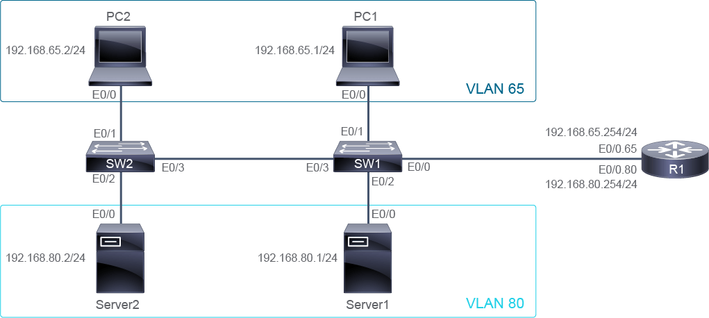
Job Aid
工作輔助資料
Device Information
裝置資訊
Device 裝置 | Interface 介面 | IPv4 Address IPv4 位址 | Remote 遠端 | Interface 介面 | VLAN VLAN |
R1 R1 | E0/0.65 E0/0.65 | 192.168.65.254/24 192.168.65.254/24 | SW1 SW1 | E0/0 E0/0 | Trunk 中繼 |
R1 R1 | E0/0.80 E0/0.80 | 192.168.80.254/24 192.168.80.254/24 | SW1 SW1 | E0/0 E0/0 | Trunk 中繼 |
PC1 PC1 | E0/0 E0/0 | 192.168.65.1/24 192.168.65.1/24 | SW1 SW1 | E0/1 E0/1 | 65 65 |
Server1 Server1 | E0/0 E0/0 | 192.168.80.1/24 192.168.80.1/24 | SW1 SW1 | E0/2 E0/2 | 80 80 |
PC2 PC2 | E0/0 E0/0 | 192.168.65.2/24 192.168.65.2/24 | SW2 SW2 | E0/1 E0/1 | 65 65 |
Server2 Server2 | E0/0 E0/0 | 192.168.80.2/24 192.168.80.2/24 | SW2 SW2 | E0/2 E0/2 | 80 80 |
SW1 SW1 | E0/3 E0/3 | Trunk 中繼 | SW2 SW2 | E0/3 E0/3 | Trunk 中繼 |
VLAN Name Information
VLAN 名稱資訊
VLAN VLAN | Name 名稱 |
65 65 | Users Users |
80 80 | Servers Servers |
Configuration Tips
設定提示
- Ensure that both switches have the same VLAN numbers and names, so that traffic from one switch can connect through the trunk to ports on the other switch.確保兩台交換器上的 VLAN 編號與名稱相同,讓來自一台交換器的流量能透過中繼連接到另一台交換器上的連接埠。
- On switches, use the
switchport trunk encapsulation dot1qcommand to specify the type of trunk encapsulation before configuring a port as a trunk.在交換器上,於將連接埠設定為中繼之前,先使用switchport trunk encapsulation dot1q指令指定中繼封裝的類型。 - Use the
encapsulation dot1q vlanvlan-id command to configure router subinterfaces to use 802.1Q encapsulation.使用encapsulation dot1q vlanvlan-id 指令,將路由器子介面設定為使用 802.1Q 封裝。 - Ensure that the router R1 subinterfaces are configured with appropriate IPv4 addresses and corresponding VLANs.確保路由器 R1 的子介面已設定適當的 IPv4 位址與對應的 VLAN。
- Use
pingandtraceroutecommands to verify the connectivity.使用ping與traceroute指令驗證連線能力。
Answer Key
解答手冊
You need to complete the following tasks:
你需要完成以下任務:
- Implement the VLAN assignments on switches SW1 and SW2 as per topology and Job Aid.依照拓樸與工作輔助資料,在交換器 SW1 與 SW2 上實作 VLAN 指派。
- Use the configuration commands that are shown below to add the VLANs on switch SW1.使用下方所示的設定指令,在交換器 SW1 上新增 VLAN。
SW1(config)# vlan 65 SW1(config-vlan)# name Users SW1(config-vlan)# vlan 80 SW1(config-vlan)# name Servers SW1(config-vlan)# exit- Use the configuration commands that are shown below to add the VLANs on switch SW2.使用下方所示的設定指令,在交換器 SW2 上新增 VLAN。
SW2(config)# vlan 65 SW2(config-vlan)# name Users SW2(config-vlan)# vlan 80 SW2(config-vlan)# name Servers SW2(config-vlan)# exit- Use the configuration commands that are shown below to configure the VLAN assignment of the port connected to PC1.使用下方所示的設定指令,設定連接到 PC1 的連接埠的 VLAN 指派。
SW1(config)# interface E0/1 SW1(config-if)# switchport mode accessSW1(config-if)# switchport access vlan 65- Use the configuration commands that are shown below to configure the VLAN assignment of the port connected to PC2.使用下方所示的設定指令,設定連接到 PC2 的連接埠的 VLAN 指派。
SW2(config)# interface E0/1 SW2(config-if)# switchport mode access SW2(config-if)# switchport access vlan 65- Use the configuration commands that are shown below to configure the VLAN assignment of the port connected to Server 1.使用下方所示的設定指令,設定連接到 Server1 的連接埠的 VLAN 指派。
SW1(config)# interface E0/2 SW1(config-if)# switchport mode access SW1(config-if)# switchport access vlan 80- Use the configuration commands that are shown below to configure the VLAN assignment of the port connected to Server 2.使用下方所示的設定指令,設定連接到 Server2 的連接埠的 VLAN 指派。
SW2(config)# interface E0/2 SW2(config-if)# switchport mode access SW2(config-if)# switchport access vlan 80 - Configure an IEEE 802.1Q trunk between switches SW1 and SW2.在交換器 SW1 與 SW2 之間設定 IEEE 802.1Q 中繼。
- Use the commands that are shown below to implement the trunk configuration on interface E0/3 of switch SW1.使用下方所示的指令,在交換器 SW1 的介面 E0/3 上實作中繼設定。
SW1(config)# interface E0/3 SW1(config-if)# switchport trunk encapsulation dot1q SW1(config-if)# switchport mode trunk- Use the commands that are shown below to implement trunk configuration on interface E0/3 of switch SW2.使用下方所示的指令,在交換器 SW2 的介面 E0/3 上實作中繼設定。
SW2(config)# interface E0/3 SW2(config-if)# switchport trunk encapsulation dot1q SW2(config-if)# switchport mode trunk - Configure an IEEE 802.1Q trunk between switch SW1 and router R1. Use the interface labeling and IPv4 addresses provided in the Job Aid.在交換器 SW1 與路由器 R1 之間設定 IEEE 802.1Q 中繼,使用工作輔助資料中提供的介面標示與 IPv4 位址。
- Use the commands that are shown below to implement trunk configuration on interface E0/0 of switch SW1.使用下方所示的指令,在交換器 SW1 的介面 E0/0 上實作中繼設定。
SW1(config)# interface E0/0 SW1(config-if)# switchport trunk encapsulation dot1q SW1(config-if)# switchport mode trunk- Use the commands that are shown below to configure the subinterface on router R1 for VLAN 65 and use 802.1Q trunk encapsulation.使用下方所示的指令,在路由器 R1 上為 VLAN 65 設定子介面,並使用 802.1Q 中繼封裝。
R1(config)# interface 0/0.65 R1(config-subif)# encapsulation dot1q 65 R1(config-subif)# ip address 192.168.65.254 255.255.255.0 R1(config-subif)#- Use the commands that are shown below to configure the subinterface on router R1 for VLAN 80 and use 802.1Q trunk encapsulation.使用下方所示的指令,在路由器 R1 上為 VLAN 80 設定子介面,並使用 802.1Q 中繼封裝。
R1(config)# interface e0/0.80 R1(config-subif)# encapsulation dot1q 80 R1(config-subif)# ip address 192.168.80.254 255.255.255.0 - Verify that there is connectivity among the servers and PCs in the lab. Verify that router R1 is included in the path of the communication between devices from different VLANs.驗證實驗中伺服器與 PC 之間具有連線能力,並確認路由器 R1 位於不同 VLAN 裝置之間通訊的路徑上。
- Verify that the status of the trunk between switches SW1 and SW2 is up and working.驗證交換器 SW1 與 SW2 之間中繼的狀態為啟用且正常運作。
SW1# show interface trunk Port Mode Encapsulation Status Native vlan Et0/3 on 802.1q trunking 1 Port Vlans allowed on trunk Et0/3 1-4094 Port Vlans allowed and active in management domain Et0/3 1,65,80 Port Vlans in spanning tree forwarding state and not pruned Et0/3 1 SW2# show interface trunk Port Mode Encapsulation Status Native vlan Et0/3 on 802.1q trunking 1 Port Vlans allowed on trunk Et0/3 1-4094 Port Vlans allowed and active in management domain Et0/3 1,65,80 Port Vlans in spanning tree forwarding state and not pruned Et0/3 1- Verify connectivity between devices on the same VLAN on different switches.驗證不同交換器上、位於同一 VLAN 的裝置之間具有連線能力。
Server1# ping 192.168.80.2 Sending 5, 100-byte ICMP Echo Packets to 192.168.80.2, timeout is 2 seconds !!!!! Success rate is 100 percent (5/5), round-trip min/avg/max = 1/1/1 ms PC1# ping 192.168.65.2 Sending 5, 100-byte ICMP Echo Packets to 192.168.65.2, timeout is 2 seconds !!!!! Success rate is 100 percent (5/5), round-trip min/avg/max = 1/1/1 ms- Verify that the router-on-a-stick configuration is working by checking connectivity between devices on the different VLANs. Verify using the
show running-configuration interfacecommand and ping responses from devices on the different VLANs.透過檢查不同 VLAN 裝置之間的連線能力,驗證單臂路由設定是否正常運作。請使用show running-configuration interface指令與不同 VLAN 裝置的 ping 回應進行驗證。
R1# show running-config interface e0/0.65 Building configuration... Current configuration : 97 bytes ! interface Ethernet0/0.65 encapsulation dot1q 65 ip address 192.168.65.254 255.255.255.0 end R1# show running-config interface e0/0.80 Building configuration... Current configuration : 97 bytes ! interface Ethernet0/0.80 encapsulation dot1q 80 ip address 192.168.80.254 255.255.255.0 end Server1# ping 192.168.65.2 Type escape sequence to abort. Sending 5, 100-byte ICMP Echos to 192.168.65.2, timeout is 2 seconds: !!!!! Success rate is 100 percent (5/5), round-trip min/avg/max = 1/1/2 ms Server1# PC1# ping 192.168.80.2Sending 5, 100-byte ICMP Echo Packets to 192.168.80.2, timeout is 2 seconds !!!!! Success rate is 100 percent (5/5), round-trip min/avg/max = 1/1/1 ms- Check the connectivity between the server VLAN and the router VLAN.檢查伺服器 VLAN 與路由器 VLAN 之間的連線能力。
Implement Multiple VLANs and Basic Routing Between the VLANs Questions
「實作多個 VLAN 並在其間進行基本路由」問題
Which command displays the output below on the SW1 switch? VLAN Name Status Ports
---- -------------------------------- --------- -------------------------------
1 default active
65 Users active Et0/1
80 Servers active Et0/2
1002 fddi-default act/unsup
1003 token-ring-default act/unsup
1004 fddinet-default act/unsup
1005 trnet-default act/unsup
哪個指令會在 SW1 交換器上顯示以下輸出?VLAN Name Status Ports
---- -------------------------------- --------- -------------------------------
1 default active
65 Users active Et0/1
80 Servers active Et0/2
1002 fddi-default act/unsup
1003 token-ring-default act/unsup
1004 fddinet-default act/unsup
1005 trnet-default act/unsup
---- -------------------------------- --------- -------------------------------
1 default active
65 Users active Et0/1
80 Servers active Et0/2
1002 fddi-default act/unsup
1003 token-ring-default act/unsup
1004 fddinet-default act/unsup
1005 trnet-default act/unsup
哪個指令會在 SW1 交換器上顯示以下輸出?VLAN Name Status Ports
---- -------------------------------- --------- -------------------------------
1 default active
65 Users active Et0/1
80 Servers active Et0/2
1002 fddi-default act/unsup
1003 token-ring-default act/unsup
1004 fddinet-default act/unsup
1005 trnet-default act/unsup
Which command displays the output below on the SW2 switch? Port Mode Encapsulation Status Native vlan
Et0/3 on 802.1q trunking 1
Port Vlans allowed on trunk
Et0/3 1-4094
Port Vlans allowed and active in management domain
Et0/3 1,65,80
Port Vlans in spanning tree forwarding state and not pruned
Et0/3 1,65,80哪個指令會在 SW2 交換器上顯示以下輸出?Port Mode Encapsulation Status Native vlan
Et0/3 on 802.1q trunking 1
Port Vlans allowed on trunk
Et0/3 1-4094
Port Vlans allowed and active in management domain
Et0/3 1,65,80
Port Vlans in spanning tree forwarding state and not pruned
Et0/3 1,65,80
Et0/3 on 802.1q trunking 1
Port Vlans allowed on trunk
Et0/3 1-4094
Port Vlans allowed and active in management domain
Et0/3 1,65,80
Port Vlans in spanning tree forwarding state and not pruned
Et0/3 1,65,80哪個指令會在 SW2 交換器上顯示以下輸出?Port Mode Encapsulation Status Native vlan
Et0/3 on 802.1q trunking 1
Port Vlans allowed on trunk
Et0/3 1-4094
Port Vlans allowed and active in management domain
Et0/3 1,65,80
Port Vlans in spanning tree forwarding state and not pruned
Et0/3 1,65,80
When performing ping from Server1, which verification is successful?從 Server1 執行 ping 時,哪一項驗證會成功?