Introduction
簡介
This activity will guide you through the exploration of packet forwarding. The lab is prepared with the devices as represented in the topology diagram. The devices are fully configured, including static routing on the routers. MAC addresses in your outputs may be different from the MAC addresses displayed in the outputs in this activity.
此活動將引導你探索封包轉送。實驗室已依拓樸圖所示完成裝置設定,裝置皆已完整設定,包括路由器上的靜態路由。你輸出結果中的 MAC 位址,可能與此活動輸出範例中顯示的 MAC 位址不同。
Topology
拓樸
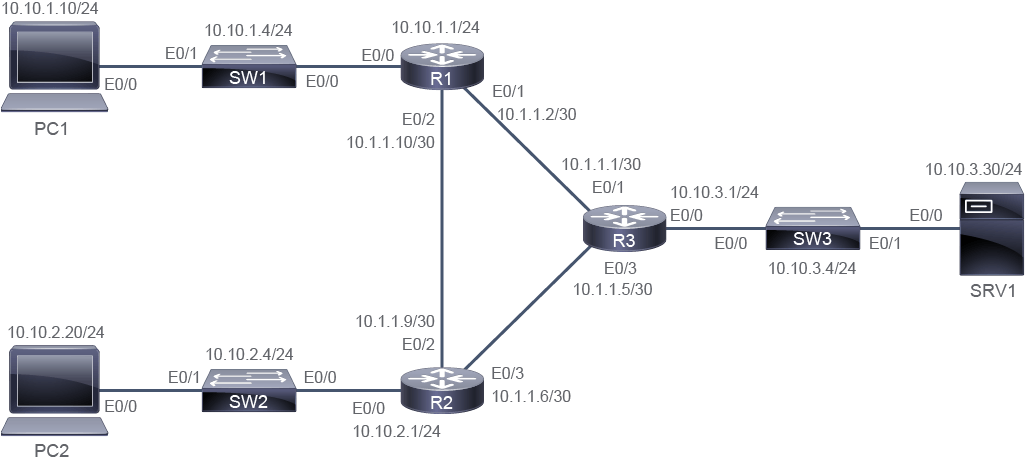
Job Aid
輔助資料
Device Information
裝置資訊
Device Information Table
裝置資訊表
Device 裝置 | Characteristic 特性 | Value 值 |
PC1 PC1 | IPv4 address IPv4 位址 | 10.10.1.10/24 10.10.1.10/24 |
PC1 PC1 | Default gateway 預設閘道 | 10.10.1.1 10.10.1.1 |
PC2 PC2 | IPv4 address IPv4 位址 | 10.10.2.20/24 10.10.2.20/24 |
PC2 PC2 | Default gateway 預設閘道 | 10.10.2.1 10.10.2.1 |
SRV1 SRV1 | IPv4 address IPv4 位址 | 10.10.3.30/24 10.10.3.30/24 |
SRV1 SRV1 | Default gateway 預設閘道 | 10.10.3.1 10.10.3.1 |
SW1 SW1 | VLAN 1 IPv4 address VLAN 1 IPv4 位址 | 10.10.1.4/24 10.10.1.4/24 |
SW1 SW1 | Default gateway 預設閘道 | 10.10.1.1 10.10.1.1 |
SW1 SW1 | Ethernet0/0 description Ethernet0/0 描述 | Link to R1 連接到 R1 |
SW1 SW1 | Ethernet0/1 description Ethernet0/1 描述 | Link to PC1 連接到 PC1 |
SW2 SW2 | VLAN 1 IPv4 address VLAN 1 IPv4 位址 | 10.10.2.4/24 10.10.2.4/24 |
SW2 SW2 | Default gateway 預設閘道 | 10.10.2.1 10.10.2.1 |
SW2 SW2 | Ethernet0/0 description Ethernet0/0 描述 | Link to R2 連接到 R2 |
SW2 SW2 | Ethernet0/1 Description Ethernet0/1 描述 | Link to PC2 連接到 PC2 |
SW3 SW3 | VLAN 1 IPv4 address VLAN 1 IPv4 位址 | 10.10.3.4/24 10.10.3.4/24 |
SW3 SW3 | Default gateway 預設閘道 | 10.10.3.1 10.10.3.1 |
SW3 SW3 | Ethernet0/0 description Ethernet0/0 描述 | Link to R3 連接到 R3 |
SW3 SW3 | Ethernet0/1 description Ethernet0/1 描述 | Link to SRV1 連接到 SRV1 |
R1 R1 | Ethernet0/0 description Ethernet0/0 描述 | Link to SW1 連接到 SW1 |
R1 R1 | Ethernet0/0 IPv4 address Ethernet0/0 IPv4 位址 | 10.10.1.1/24 10.10.1.1/24 |
R1 R1 | Ethernet0/1 description Ethernet0/1 描述 | Link to R3 連接到 R3 |
R1 R1 | Ethernet0/1 IPv4 address Ethernet0/1 IPv4 位址 | 10.1.1.2/30 10.1.1.2/30 |
R1 R1 | Ethernet0/2 description Ethernet0/2 描述 | Link to R2 連接到 R2 |
R1 R1 | Ethernet0/2 IPv4 address Ethernet0/2 IPv4 位址 | 10.1.1.10/30 10.1.1.10/30 |
R2 R2 | Ethernet0/0 description Ethernet0/0 描述 | Link to SW2 連接到 SW2 |
R2 R2 | Ethernet0/0 IPv4 address Ethernet0/0 IPv4 位址 | 10.10.2.1/24 10.10.2.1/24 |
R2 R2 | Ethernet0/2 description Ethernet0/2 描述 | Link to R1 連接到 R1 |
R2 R2 | Ethernet0/2 IPv4 address Ethernet0/2 IPv4 位址 | 10.1.1.9/30 10.1.1.9/30 |
R2 R2 | Ethernet0/3 description Ethernet0/3 描述 | Link to R3 連接到 R3 |
R2 R2 | Ethernet0/3 IPv4 address Ethernet0/3 IPv4 位址 | 10.1.1.6/30 10.1.1.6/30 |
R3 R3 | Ethernet0/0 description Ethernet0/0 描述 | Link to SW3 連接到 SW3 |
R3 R3 | Ethernet0/0 IPv4 address Ethernet0/0 IPv4 位址 | 10.10.3.1/24 10.10.3.1/24 |
R3 R3 | Ethernet0/1 description Ethernet0/1 描述 | Link to R1 連接到 R1 |
R3 R3 | Ethernet0/1 IPv4 address Ethernet0/1 IPv4 位址 | 10.1.1.1/30 10.1.1.1/30 |
R3 R3 | Ethernet0/3 description Ethernet0/3 描述 | Link to R2 連接到 R2 |
R3 R3 | Ethernet0/3 IPv4 address Ethernet0/3 IPv4 位址 | 10.1.1.5/30 10.1.1.5/30 |
Task 1: Explore Packet Forwarding
任務 1:探索封包轉送
Activity
活動
Observe the topology diagram. This activity will focus on the forwarding of packets from PC1 to SRV1.
觀察拓樸圖。此活動將著重於封包從 PC1 轉送到 SRV1 的過程。
The devices in the path between these two hosts are SW1, R1, R3, and SW3.
位於這兩台主機之間路徑上的裝置為 SW1、R1、R3 與 SW3。
Access the console of PC1, and verify connectivity to SRV1 using the ping and traceroute commands.
存取 PC1 的主控台,並使用 ping 與 traceroute 指令驗證與 SRV1 之間的連線。
PC1# ping 10.10.3.30
Type escape sequence to abort.
Sending 5, 100-byte ICMP Echos to 10.10.3.30, timeout is 2 seconds:
.!!!
Success rate is 80 percent (4/5), round-trip min/avg/max = 1/1/1 ms
PC1# traceroute 10.10.3.30
Type escape sequence to abort.
Tracing the route to 10.10.3.30
VRF info: (vrf in name/id, vrf out name/id)
  1 10.10.1.1 1 msec 0 msec 0 msec
  2 10.1.1.1 1 msec 0 msec 1 msec
  3 10.10.3.30 0 msec *  1 msec
The traceroute output shows 10.10.1.1 and 10.1.1.1 is in the forwarding path to SRV1. These addresses belong to Ethernet0/0 on R1 and Ethernet0/1 on R3. The interfaces Ethernet0/1 on R1 and Ethernet0/0 on R3 are also involved in the forwarding process, as are the switches SW1 and SW3.
traceroute 的輸出顯示,10.10.1.1 與 10.1.1.1 位於通往 SRV1 的轉送路徑上。這兩個位址分別屬於 R1 的 Ethernet0/0 與 R3 的 Ethernet0/1。R1 的 Ethernet0/1 與 R3 的 Ethernet0/0 介面,以及交換器 SW1 與 SW3,也都參與了轉送程序。
One at a time, access the consoles of PC1, R1, R3, and SRV1, and use the show interfaces command to inventory the IPv4 addresses and MAC addresses on the interfaces that are involved in the forwarding process.
依序存取 PC1、R1、R3 與 SRV1 的主控台,並使用 show interfaces 指令,盤點參與轉送程序之介面上的 IPv4 位址與 MAC 位址。
The information that you need is in the output of the show interfaces command, but to focus explicitly on the data that you are interested in. It would be useful to send the output through the include filter and only display lines that contain the string address.
你所需要的資訊都在 show interfaces 指令的輸出中,但為了明確聚焦於你感興趣的資料,可以將輸出透過 include 過濾器,只顯示包含字串 address 的那幾行,這樣會更有幫助。
PC1# show interfaces Ethernet0/0
Ethernet0/0 is up, line protocol is up
  Hardware is AmdP2, address is aabb.cc00.0400 (bia aabb.cc00.0400)
  Internet address is 10.10.1.10/24
  MTU 1500 bytes, BW 10000 Kbit/sec, DLY 1000 usec,
     reliability 255/255, txload 1/255, rxload 1/255
  Encapsulation ARPA, loopback not set
  Keepalive set (10 sec)
  ARP type: ARPA, ARP Timeout 04:00:00
  Last input 00:00:01, output 00:00:07, output hang never
  Last clearing of "show interface" counters never
  Input queue: 0/75/0/0 (size/max/drops/flushes); Total output drops: 0
  Queueing strategy: fifo
  Output queue: 0/40 (size/max)
  5 minute input rate 0 bits/sec, 0 packets/sec
  5 minute output rate 0 bits/sec, 0 packets/sec
     1470 packets input, 93664 bytes, 0 no buffer
     Received 1229 broadcasts (0 IP multicasts)
     0 runts, 0 giants, 0 throttles
     0 input errors, 0 CRC, 0 frame, 0 overrun, 0 ignored
     0 input packets with dribble condition detected
     311 packets output, 34770 bytes, 0 underruns
     0 output errors, 0 collisions, 1 interface resets
     2 unknown protocol drops
     0 babbles, 0 late collision, 0 deferred
     0 lost carrier, 0 no carrier
     0 output buffer failures, 0 output buffers swapped out
This example illustrated the full command syntax of the show interfaces command. The examples that follow will utilize command abbreviations.
此範例展示了 show interfaces 指令的完整語法。之後的範例將會使用縮寫指令。
Note that the string that is passed to the include filter cannot be abbreviated. Cisco IOS Software cannot determine that when you use the string add that you intend for it to be an abbreviation of address. But the only appearance of the string add in the command output is as a substring of address; therefore, it would be an acceptable string to use for this purpose.
請注意,傳遞給 include 過濾器的字串不能縮寫。Cisco IOS 軟體無法判斷當你使用字串 add 時,是打算將它作為 address 的縮寫。但由於字串 add 在指令輸出中唯一出現的地方,就是作為 address 的子字串,因此在此用途上使用它是可以被接受的。
R1# show interface e0/0  | include address
  Hardware is AmdP2, address is aabb.cc00.0100 (bia aabb.cc00.0100)
  Internet address is 10.10.1.1/24
R1# show interface e0/1  | include address
  Hardware is AmdP2, address is aabb.cc00.0110 (bia aabb.cc00.0110)
  Internet address is 10.1.1.2/30
R3# show interface e0/0 | include address
Hardware is AmdP2, address is aabb.cc00.0300 (bia aabb.cc00.0300)
Internet address is 10.10.3.1/24
R3# show interface e0/1 | include address
Hardware is AmdP2, address is aabb.cc00.0310 (bia aabb.cc00.0310)
Internet address is 10.1.1.1/30SRV1# show interface e0/0 | include address
Hardware is AmdP2, address is aabb.cc00.0600 (bia aabb.cc00.0600)
Internet address is 10.10.3.30/24MAC addresses may be different than shown in the example.
MAC 位址可能與範例中所顯示的不同。
The output of the show interfaces commands can be compiled for reference into a table.
可以將 show interfaces 指令的輸出整理成一張表格以供參考。
The table would appear as follows:
此表格內容如下:
MAC addresses may be different than shown in the example.
MAC 位址可能與範例中所顯示的不同。
Device 裝置 | Interface 介面 | MAC Address MAC 位址 | IPv4 Address IPv4 位址 |
PC1 PC1 | Ethernet0/0 Ethernet0/0 | aabb.cc00.0400 aabb.cc00.0400 | 10.10.1.10 10.10.1.10 |
R1 R1 | Ethernet0/0 Ethernet0/0 | aabb.cc00.0100 aabb.cc00.0100 | 10.10.1.1 10.10.1.1 |
R1 R1 | Ethernet0/1 Ethernet0/1 | aabb.cc00.0110 aabb.cc00.0110 | 10.1.1.2 10.1.1.2 |
R3 R3 | Ethernet0/0 Ethernet0/0 | aabb.cc00.0300 aabb.cc00.0300 | 10.10.3.1 10.10.3.1 |
R3 R3 | Ethernet0/1 Ethernet0/1 | aabb.cc00.0310 aabb.cc00.0310 | 10.1.1.1 10.1.1.1 |
SRV1 SRV1 | Ethernet0/0 Ethernet0/0 | aabb.cc00.0600 aabb.cc00.0600 | 10.10.3.30 10.10.3.30 |
When PC1 generates an IPv4 packet for SRV1, it will encapsulate the data with an IPv4 header specifying 10.10.3.30 as the destination IPv4 address and 10.10.1.10 as the source IPv4 address. It will then encapsulate the IPv4 packet with an Ethernet header specifying the Ethernet0/0 MAC address in R1 (aabb.cc00.0100 in this example) as the destination MAC address and its own MAC address (aabb.cc00.0400 in this example) as the source. PC1 obtains the MAC address of R1 from its ARP cache. Access the console of PC1 and display its ARP cache.
當 PC1 為 SRV1 產生一個 IPv4 封包時,會以 IPv4 標頭封裝該資料,指定 10.10.3.30 為目的 IPv4 位址、10.10.1.10 為來源 IPv4 位址。接著它會以乙太網路標頭封裝此 IPv4 封包,指定 R1 上 Ethernet0/0 的 MAC 位址(在此範例中為 aabb.cc00.0100)為目的 MAC 位址,並以自己的 MAC 位址(在此範例中為 aabb.cc00.0400)作為來源。PC1 是從其 ARP 快取中取得 R1 的 MAC 位址。存取 PC1 的主控台並顯示其 ARP 快取。
The entry for 10.10.1.1 was populated in the ARP table when you performed the ping operation at the beginning of this discovery.
10.10.1.1 的項目,是在你於此探索活動一開始執行 ping 操作時填入 ARP 表的。
PC1# show ip arp
Protocol  Address          Age (min)  Hardware Addr   Type   Interface
Internet  10.10.1.1              45   aabb.cc00.0100  ARPA   Ethernet0/0
Internet  10.10.1.10              -   aabb.cc00.0400  ARPA   Ethernet0/0
MAC addresses may be different than shown in the example.
MAC 位址可能與範例中所顯示的不同。
Execute the following sequence of commands to observe the behavior of the ARP process. Execute the debug arp command to enable debugging of ARP packets and use the show commands to provide visibility into the process. Shut down the Ethernet0/0 interface of PC1 to clear the ARP cache entries associated with the interface. Next, re-enable the interface and initiate connectivity; both actions will stimulate ARP activity. The informative notes that are embedded in the directions further explain the operations.
執行下列一連串指令,以觀察 ARP 程序的行為。執行 debug arp 指令,以啟用 ARP 封包除錯功能,並使用 show 指令提供對此程序的可視性。關閉 PC1 的 Ethernet0/0 介面,以清除與該介面相關的 ARP 快取項目。接著,重新啟用該介面並發起連線,這兩個動作都會觸發 ARP 活動。指示中內嵌的說明將進一步解釋這些操作。
On PC1, enable debugging of ARP packets:
在 PC1 上,啟用 ARP 封包的除錯功能:
PC1# debug arp
ARP packet debugging is on
Be very careful when using debug commands in production environments. Depending on the circumstances, they can have a catastrophic effect on router performance. Until you have experience with debug commands, it is best to consult a senior engineer within your organization on their use.
在正式環境中使用 debug 指令時務必格外小心。視情況而定,它們可能對路由器效能造成災難性的影響。在你熟悉 debug 指令的使用之前,最好先向組織中資深工程師諮詢其用法。
PC1# configure terminal
Enter configuration commands, one per line.  End with CNTL/Z.
PC1(config)# interface Ethernet 0/0
PC1(config-if)# do show ip arp
Protocol  Address          Age (min)  Hardware Addr   Type   Interface
Internet  10.10.1.1              51   aabb.cc00.0100  ARPA   Ethernet0/0
Internet  10.10.1.10              -   aabb.cc00.0400  ARPA   Ethernet0/0
The do command allows access to EXEC mode commands from within the configuration mode. The show ip arp command verifies that the two entries are still in the ARP cache.
do 指令可讓你在設定模式中存取 EXEC 模式的指令。show ip arp 指令可驗證這兩筆項目是否仍存在於 ARP 快取中。
PC1(config-if)# shutdown
PC1(config-if)#
*Oct  9 12:40:03.589: %LINK-5-CHANGED: Interface Ethernet0/0, changed state to administratively down
*Oct  9 12:40:04.589: %LINEPROTO-5-UPDOWN: Line protocol on Interface Ethernet0/0, changed state to down
PC1(config-if)# do show ip arp
PC1(config-if)#
This time, there is no output from the show ip arp command. The ARP cache on PC1 is currently empty. The entries that are associated with Ethernet0/0 were cleared when the interface was shut down.
這次,show ip arp 指令沒有任何輸出。PC1 目前的 ARP 快取是空的。與 Ethernet0/0 相關的項目,已在該介面被關閉時被清除。
PC1(config-if)# no shutdown
PC1(config-if)#
*Oct  9 12:41:24.437: IP ARP: sent rep src 10.10.1.10 aabb.cc00.0400,
                 dst 10.10.1.10 ffff.ffff.ffff Ethernet0/0
*Oct  9 12:41:24.437: IP ARP: sent rep src 10.10.1.10 aabb.cc00.0400,
                 dst 10.10.1.10 ffff.ffff.ffff Ethernet0/0
The two preceding messages are debugging messages. Note that they are both ARP "rep" frames, which are reply frames. The destination IPv4 address is 10.10.1.10. PC1 is sending this ARP broadcast asking any host with the IPv4 address 10.10.1.10, which is its own address, to respond with an ARP reply. Cisco IOS Software sends this ARP broadcast automatically when interfaces are brought online. It is an attempt to recognize when there are duplicate IPv4 addresses on the network. If any responses are received, system logging (syslog) messages would be generated to alert the network administrator that there are duplicate addresses. No replies were received, which is normal.
前面兩則訊息是除錯訊息。請注意,這兩則都是 ARP「rep」框架,也就是回覆框架。目的 IPv4 位址為 10.10.1.10。PC1 正在送出這則 ARP 廣播,詢問任何 IPv4 位址為 10.10.1.10(也就是它自己的位址)的主機以 ARP 回覆做回應。當介面上線時,Cisco IOS 軟體會自動送出此 ARP 廣播,目的是嘗試辨識網路上是否存在重複的 IPv4 位址。如果收到任何回應,就會產生系統記錄(syslog)訊息,以提醒網路管理員有位址重複的情況。此處沒有收到任何回覆,這是正常現象。
*Oct  9 12:41:26.434: %LINK-3-UPDOWN: Interface Ethernet0/0, changed state to up
*Oct  9 12:41:27.434: %LINEPROTO-5-UPDOWN: Line protocol on Interface Ethernet0/0, changed state to up
These two messages are the normal syslog messages, which are generated when interfaces change their state. Exit configuration mode.
這兩則訊息是正常的 syslog 訊息,會在介面狀態改變時產生。離開設定模式。
PC1(config-if)# end
PC1#
You just left configuration mode. The rest of this exploration will be completed from privileged EXEC. First, ping SRV1 from PC1.
你剛剛離開了設定模式。接下來的探索都將在特權 EXEC 模式下完成。首先,從 PC1 ping SRV1。
PC1# ping 10.10.3.30
Type escape sequence to abort.
Sending 5, 100-byte ICMP Echos to 10.10.3.30, timeout is 2 seconds:
!!!!!
Success rate is 100 percent (5/5), round-trip min/avg/max = 1/1/1 ms
For this ping operation from PC1 to SRV1 to complete, PC1 must forward the packets in a frame to R1, for R1 to forward to R3. PC1 needs to know the MAC address of R1 to forward the packets to R1.
若要完成從 PC1 到 SRV1 的這次 ping 操作,PC1 必須將封包以框架轉送給 R1,再由 R1 轉送給 R3。PC1 需要知道 R1 的 MAC 位址,才能將封包轉送給 R1。
*Oct 9 12:41:27.434: IP ARP: creating incomplete entry for IP address: 10.10.1.1 interface Ethernet0/0This debug message indicates that PC1 recognizes that it needs the MAC address for 10.10.1.1 (R1, its default gateway). PC1 creates an entry in its ARP cache and starts the ARP process.
這則除錯訊息顯示,PC1 察覺自己需要 10.10.1.1(R1,其預設閘道)的 MAC 位址。PC1 會在其 ARP 快取中建立一筆項目,並開始 ARP 程序。
*Oct  9 12:41:27.434: IP ARP: sent req src 10.10.1.10 aabb.cc00.0400,
                 dst 10.10.1.1 0000.0000.0000 Ethernet0/0
This debug message indicates that PC1 sent an ARP request specifying 10.10.1.1 as the destination; the 0000.0000.0000 field in the request is a placeholder because PC1 does not know the MAC address (which is why it is sending the ARP request). This ARP request is broadcast to all hosts within the broadcast domain (we don’t see the broadcast in the debug output). PC1 is requesting any system with the IPv4 address 10.10.1.1 to respond with an ARP reply.
這則除錯訊息顯示,PC1 送出了一個以 10.10.1.1 為目的地的 ARP 請求;請求中的 0000.0000.0000 欄位是一個佔位符,因為 PC1 並不知道 MAC 位址(這正是它送出 ARP 請求的原因)。此 ARP 請求會廣播給廣播網域內的所有主機(我們在除錯輸出中看不到這個廣播)。PC1 正在請求任何 IPv4 位址為 10.10.1.1 的系統以 ARP 回覆做回應。
*Oct 9 12:41:27.435: IP ARP: rcvd rep src 10.10.1.1 aabb.cc00.0100, dst 10.10.1.10 Ethernet0/0This debug message indicates that PC1 received an ARP reply from 10.10.1.1, indicating that its MAC address is aabb.cc00.0100.
這則除錯訊息顯示,PC1 收到了來自 10.10.1.1 的 ARP 回覆,指出其 MAC 位址為 aabb.cc00.0100。
View the ARP cache on PC1, which is a result of the exchange of ARP packets that you just witnessed.
檢視 PC1 上的 ARP 快取,這是你剛才所看到的 ARP 封包交換之結果。
The ARP cache of PC1 now has an entry that is mapping the IPv4 address of R1 to the MAC address of R1. It also has ARP entry of its own address.
PC1 的 ARP 快取現在有一筆項目,將 R1 的 IPv4 位址對應到 R1 的 MAC 位址。此外也有它自己位址的 ARP 項目。
PC1# show ip arp
Protocol  Address          Age (min)  Hardware Addr   Type   Interface
Internet  10.10.1.1               8   aabb.cc00.0100  ARPA   Ethernet0/0
Internet 10.10.1.10 - aabb.cc00.0400 ARPA Ethernet0/0The close inspection of the ARP process is complete. Turn off the debug operations by using undebug all command.
對 ARP 程序的詳細檢視已經完成。使用 undebug all 指令關閉除錯操作。
Debug can be turned off on a per classification basis. That is, you could have used undebug arp to turn off the debug process that you started with the debug arp command.
除錯功能可以依類別個別關閉。也就是說,你也可以使用 undebug arp,來關閉你用 debug arp 指令啟動的除錯程序。
PC1# undebug all
All possible debugging has been turned off
A common abbreviation that is used for undebug all is u all.
undebug all 常見的縮寫是 u all。
The lab environment does not support capturing packets on the interface links, but the preceding results support the following extrapolation, which describes how a packet is forwarded from PC1 to SRV1:
此實驗室環境不支援在介面鏈路上擷取封包,但前述結果支持以下的推論,描述封包如何從 PC1 轉送至 SRV1:
- The IPv4 header remains constant across the entire path; the IPv4 header will specify 10.10.3.30 as the destination IPv4 address and 10.10.1.10 as the source IPv4 address.IPv4 標頭在整條路徑上保持不變;此 IPv4 標頭會指定 10.10.3.30 為目的 IPv4 位址,10.10.1.10 為來源 IPv4 位址。
- A unique Layer 2 header is used to traverse each network segment.每經過一個網路區段,就會使用一個獨立的第 2 層標頭。
- PC1 and R1 learn the MAC addresses of each other via ARP.PC1 與 R1 會透過 ARP 學習到彼此的 MAC 位址。
- R1 and R3 learn the MAC addresses of each other via ARP.R1 與 R3 會透過 ARP 學習到彼此的 MAC 位址。
- SRV1 and R3 learn the MAC addresses of each other via ARP.SRV1 與 R3 會透過 ARP 學習到彼此的 MAC 位址。
- PC1 will encapsulate the IPv4 packet with an Ethernet header that specifies aabb.cc00.0100 (R1 Ethernet0/0) as the destination MAC address and aabb.cc00.0400 (PC1) as the source MAC address.PC1 會以乙太網路標頭封裝此 IPv4 封包,指定 aabb.cc00.0100(R1 的 Ethernet0/0)為目的 MAC 位址,aabb.cc00.0400(PC1)為來源 MAC 位址。
- PC1 will send this packet out of its Ethernet0/0 interface, and R1 will receive it on its Ethernet0/0 interface.PC1 會將此封包從其 Ethernet0/0 介面送出,R1 則會在其 Ethernet0/0 介面上收到它。
- R1 will strip the Ethernet header and replace it with another Ethernet header that specifies aabb.cc00.0310 (R3 Ethernet 0/1) as the destination MAC address and aabb.cc00.0110 (R1 Ethernet0/1) as the source MAC address. R1 will send this out of its Ethernet 0/1 interface, and R3 will receive it on its Ethernet 0/1 interface.R1 會剝除該乙太網路標頭,並替換上另一個乙太網路標頭,指定 aabb.cc00.0310(R3 的 Ethernet 0/1)為目的 MAC 位址,aabb.cc00.0110(R1 的 Ethernet0/1)為來源 MAC 位址。R1 會將此封包從其 Ethernet 0/1 介面送出,R3 則會在其 Ethernet 0/1 介面上收到它。
- R3 will strip the Ethernet header and replace it with another Ethernet header that specifies aabb.cc00.0600 (SRV1) as the destination MAC address and aabb.cc00.0300 as the source MAC address. This source MAC address is the MAC address of the Ethernet 0/0 interface.R3 會剝除該乙太網路標頭,並替換上另一個乙太網路標頭,指定 aabb.cc00.0600(SRV1)為目的 MAC 位址,aabb.cc00.0300 為來源 MAC 位址。此來源 MAC 位址即為 Ethernet 0/0 介面的 MAC 位址。
- R3 will send this frame out of its Ethernet0/0 interface, and SRV1 will receive it on its Ethernet0/0 interface.R3 會將此框架從其 Ethernet0/0 介面送出,SRV1 則會在其 Ethernet0/0 介面上收到它。
The previous steps did not depict how SW1 supports the forwarding of frames between PC1 and R1 and how SW3 supports the forwarding of frames between R3 and SRV1. Switches learn which ports connect to devices with which MAC addresses based on examining the source MAC address on incoming frames. When they know which ports lead to which MAC addresses, they can forward frames out of those ports based on the destination MAC address in frames. Access the console of SW1 and view its MAC address table.
前面的步驟並未描繪出 SW1 如何協助在 PC1 與 R1 之間轉送框架,以及 SW3 如何協助在 R3 與 SRV1 之間轉送框架。交換器會依據檢視送入框架的來源 MAC 位址,學習哪些連接埠連接到哪些 MAC 位址的裝置。一旦知道哪些連接埠通往哪些 MAC 位址,它們就可以依據框架中的目的 MAC 位址,將框架從對應的連接埠轉送出去。存取 SW1 的主控台,並檢視其 MAC 位址表。
The MAC address of PC1 is associated with SW1 port Ethernet0/1 and the MAC address of R1 is associated with SW1 port Ethernet0/0.
PC1 的 MAC 位址與 SW1 的 Ethernet0/1 連接埠相關聯,而 R1 的 MAC 位址則與 SW1 的 Ethernet0/0 連接埠相關聯。
SW1# show mac address-table
          Mac Address Table
-------------------------------------------

Vlan    Mac Address       Type        Ports
----    -----------       --------    -----
   1    aabb.cc00.0100    DYNAMIC     Et0/0
   1    aabb.cc00.0400    DYNAMIC     Et0/1
Total Mac Addresses for this criterion: 2Clear the MAC address table on SW1 using the clear mac address-table dynamic command and display it again to verify that it is empty.
使用 clear mac address-table dynamic 指令清除 SW1 上的 MAC 位址表,並再次顯示它以確認其已清空。
The example shows an empty MAC address table, but when you attempt this step, you may see that the entries have already repopulated. If so, simply repeat the last two commands as quickly as possible (use the Up Arrow key for command recall) until you see the empty MAC address table.
此範例顯示的是一個空的 MAC 位址表,但當你實際嘗試此步驟時,可能會發現項目已經重新填入。若是如此,請盡快重複最後兩個指令(可使用向上鍵來叫回先前的指令),直到你看到空的 MAC 位址表為止。
SW1# clear mac address-table dynamic
SW1# show mac address-table
          Mac Address Table
-------------------------------------------

Vlan    Mac Address       Type        Ports
---- ----------- -------- -----Wait at least 10 seconds after viewing the empty MAC address table before continuing. Display the MAC address table one more time.
在看到空的 MAC 位址表之後,至少等待 10 秒鐘再繼續。再次顯示 MAC 位址表。
The MAC address table has again been repopulated with the MAC addresses of PC1 and R1.
MAC 位址表再次被填入了 PC1 與 R1 的 MAC 位址。
SW1# show mac address-table
          Mac Address Table
-------------------------------------------

Vlan    Mac Address       Type        Ports
----    -----------       --------    -----
   1    aabb.cc00.0100    DYNAMIC     Et0/0
   1    aabb.cc00.0400    DYNAMIC     Et0/1
Total Mac Addresses for this criterion: 2How did the table get repopulated? When the switch receives a frame of any kind, it examines the source MAC address to determine if it needs to add it to the MAC address table. By default, with Cisco IOS Software, Ethernet interfaces send frames to their own MAC address every 10 seconds as a keepalive mechanism. Verify this setting by accessing the console of PC1 and use the show interface command to view the status of Ethernet0/0.
這張表是如何重新被填入的呢?當交換器收到任何一種框架時,都會檢視其來源 MAC 位址,以判斷是否需要將其加入 MAC 位址表。在 Cisco IOS 軟體中,預設情況下,乙太網路介面每 10 秒就會將框架送給自己的 MAC 位址,作為一種保活(keepalive)機制。請透過存取 PC1 的主控台,並使用 show interface 指令檢視 Ethernet0/0 的狀態,來驗證此設定。
The keepalive value is set to 10 seconds. Also, make a note of the number of packets output from the interface.
保活數值設定為 10 秒。同時,記下該介面輸出的封包數量。
PC1# show interface e0/0
Ethernet0/0 is up, line protocol is up
  Hardware is AmdP2, address is aabb.cc00.0400 (bia aabb.cc00.0400)
  Internet address is 10.10.1.10/24
  MTU 1500 bytes, BW 10000 Kbit/sec, DLY 1000 usec,
     reliability 255/255, txload 1/255, rxload 1/255
  Encapsulation ARPA, loopback not set
 Keepalive set (10 sec)
  ARP type: ARPA, ARP Timeout 04:00:00
  Last input 00:00:00, output 00:00:09, output hang never
  Last clearing of "show interface" counters never
  Input queue: 0/75/0/0 (size/max/drops/flushes); Total output drops: 0
  Queueing strategy: fifo
  Output queue: 0/40 (size/max)
  5 minute input rate 0 bits/sec, 0 packets/sec
  5 minute output rate 0 bits/sec, 0 packets/sec
 3583 packets input, 225244 bytes, 0 no buffer
     Received 3014 broadcasts (0 IP multicasts)
     0 runts, 0 giants, 0 throttles
     0 input errors, 0 CRC, 0 frame, 0 overrun, 0 ignored
     0 input packets with dribble condition detected
 708 packets output, 76818 bytes, 0 underruns
     0 output errors, 0 collisions, 2 interface resets
     2 unknown protocol drops
     0 babbles, 0 late collision, 0 deferred
     0 lost carrier, 0 no carrier
0 output buffer failures, 0 output buffers swapped outWait 10 seconds and repeat the show interface command. Verify that the number of packets output has increased by at least 1.
等待 10 秒後,重複執行 show interface 指令,確認輸出封包數量至少增加了 1。
You now have some experience with the forwarding of packets between IPv4 hosts, including the ARP process and the use of MAC addresses on Ethernet networks. You also investigated how switches populate and use the MAC address tables. Feel free to continue exploring independently within the lab environment.
你現在已經對 IPv4 主機之間的封包轉送有了一些實務經驗,包括 ARP 程序以及乙太網路上 MAC 位址的使用方式。你也探討了交換器如何填入並使用 MAC 位址表。歡迎在此實驗室環境中自行繼續探索。
PC1# show interface e0/0
Ethernet0/0 is up, line protocol is up
  Hardware is AmdP2, address is aabb.cc00.0400 (bia aabb.cc00.0400)
  Internet address is 10.10.1.10/24
  MTU 1500 bytes, BW 10000 Kbit/sec, DLY 1000 usec,
     reliability 255/255, txload 1/255, rxload 1/255
  Encapsulation ARPA, loopback not set
  Keepalive set (10 sec)
  ARP type: ARPA, ARP Timeout 04:00:00
  Last input 00:00:00, output 00:00:00, output hang never
  Last clearing of "show interface" counters never
  Input queue: 0/75/0/0 (size/max/drops/flushes); Total output drops: 0
  Queueing strategy: fifo
  Output queue: 0/40 (size/max)
  5 minute input rate 0 bits/sec, 0 packets/sec
  5 minute output rate 0 bits/sec, 0 packets/sec
 3624 packets input, 227780 bytes, 0 no buffer
     Received 3048 broadcasts (0 IP multicasts)
     0 runts, 0 giants, 0 throttles
     0 input errors, 0 CRC, 0 frame, 0 overrun, 0 ignored
     0 input packets with dribble condition detected
 716 packets output, 77591 bytes, 0 underruns
     0 output errors, 0 collisions, 2 interface resets
     2 unknown protocol drops
     0 babbles, 0 late collision, 0 deferred
     0 lost carrier, 0 no carrier
     0 output buffer failures, 0 output buffers swapped out