Introduction
簡介
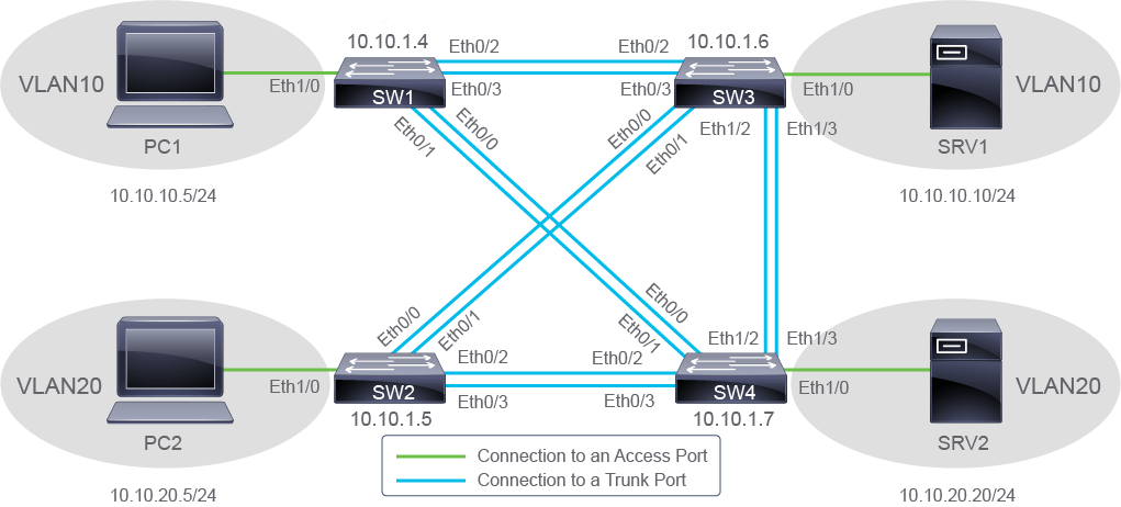
The purpose of this activity is to provide you with some experience working with EtherChannel. The live virtual lab is prepared with the switches represented in the topology diagram and the connectivity table. All devices have their basic configurations in place, including hostnames and IPv4 addresses. Note that all the links between the switches use pairs of connections. You will see that this fact does not lead to doubling of the bandwidth by default. You will configure EtherChannel on some of the links, examine how link aggregation affects STP topology for one of the VLANs, and verify the EtherChannel configuration.
本活動的目的是讓你體驗使用 EtherChannel 的操作。這個線上虛擬實驗室已依拓樸圖與連線表準備好交換器。所有裝置都已具備基本設定,包括主機名稱與 IPv4 位址。請注意,交換器之間的每條連結都使用一對連線。你會發現,這個事實預設並不會使頻寬加倍。你將在部分連結上設定 EtherChannel,觀察鏈路聚合如何影響其中一個 VLAN 的 STP 拓樸,並驗證 EtherChannel 設定。
Topology
拓樸
Job Aid
工作輔助資料
The configuration is as follows:
設定內容如下:
- All devices have their basic configurations in place, including hostnames and IP addresses.所有裝置都已具備基本設定,包括主機名稱與 IP 位址。
Device Information
裝置資訊
Device Details
裝置詳細資訊
Device 裝置 | Interface 介面 | Neighbor 鄰居 | Additional Information 其他資訊 |
SW1 SW1 | Ethernet 1/0 Ethernet 1/0 | PC1 PC1 | access port, VLAN 10 存取埠,VLAN 10 |
SW1 SW1 | Ethernet 0/0 Ethernet 0/0 | SW4 SW4 | trunk port, native VLAN - 99 中繼埠,原生 VLAN - 99 |
SW1 SW1 | Ethernet 0/1 Ethernet 0/1 | SW4 SW4 | trunk port, native VLAN - 99 中繼埠,原生 VLAN - 99 |
SW1 SW1 | Ethernet 0/2 Ethernet 0/2 | SW3 SW3 | trunk port, native VLAN - 99 中繼埠,原生 VLAN - 99 |
SW1 SW1 | Ethernet 0/3 Ethernet 0/3 | SW3 SW3 | trunk port, native VLAN - 99 中繼埠,原生 VLAN - 99 |
PC1 PC1 | Ethernet0/0 Ethernet0/0 | SW1 SW1 | IPv4 address: 10.10.10.5/24 IPv4 位址:10.10.10.5/24 |
SW2 SW2 | Ethernet 1/0 Ethernet 1/0 | PC2 PC2 | access port, VLAN 20 存取埠,VLAN 20 |
SW2 SW2 | Ethernet 0/0 Ethernet 0/0 | SW3 SW3 | trunk port, native VLAN - 99 中繼埠,原生 VLAN - 99 |
SW2 SW2 | Ethernet 0/1 Ethernet 0/1 | SW3 SW3 | trunk port, native VLAN - 99 中繼埠,原生 VLAN - 99 |
SW2 SW2 | Ethernet 0/2 Ethernet 0/2 | SW4 SW4 | trunk port, native VLAN - 99 中繼埠,原生 VLAN - 99 |
SW2 SW2 | Ethernet 0/3 Ethernet 0/3 | SW3 SW3 | trunk port, native VLAN - 99 中繼埠,原生 VLAN - 99 |
PC2 PC2 | Ethernet0/0 Ethernet0/0 | SW2 SW2 | IPv4 address: 10.10.20.5/24 IPv4 位址:10.10.20.5/24 |
SW3 SW3 | Ethernet 1/0 Ethernet 1/0 | SRV1 SRV1 | access port, VLAN 10 存取埠,VLAN 10 |
SW3 SW3 | Ethernet 0/0 Ethernet 0/0 | SW2 SW2 | trunk port, native VLAN - 99 中繼埠,原生 VLAN - 99 |
SW3 SW3 | Ethernet0/1 Ethernet0/1 | SW2 SW2 | trunk port, native VLAN - 99 中繼埠,原生 VLAN - 99 |
SW3 SW3 | Ethernet 0/2 Ethernet 0/2 | SW1 SW1 | trunk port, native VLAN - 99 中繼埠,原生 VLAN - 99 |
SW3 SW3 | Ethernet 0/3 Ethernet 0/3 | SW1 SW1 | trunk port, native VLAN - 99 中繼埠,原生 VLAN - 99 |
SW3 SW3 | Ethernet 1/2 Ethernet 1/2 | SW4 SW4 | trunk port, native VLAN - 99 中繼埠,原生 VLAN - 99 |
SW3 SW3 | Ethernet 1/3 Ethernet 1/3 | SW4 SW4 | trunk port, native VLAN - 99 中繼埠,原生 VLAN - 99 |
SRV1 SRV1 | Ethernet0/0 Ethernet0/0 | SW3 SW3 | IPv4 address: 10.10.10.10/24 IPv4 位址:10.10.10.10/24 |
SW4 SW4 | Ethernet1/0 Ethernet1/0 | SRV2 SRV2 | access port, VLAN 20 存取埠,VLAN 20 |
SW4 SW4 | Ethernet 0/0 Ethernet 0/0 | SW1 SW1 | trunk port, native VLAN - 99 中繼埠,原生 VLAN - 99 |
SW4 SW4 | Ethernet 0/1 Ethernet 0/1 | SW1 SW1 | trunk port, native VLAN - 99 中繼埠,原生 VLAN - 99 |
SW4 SW4 | Ethernet 0/2 Ethernet 0/2 | SW2 SW2 | trunk port, native VLAN - 99 中繼埠,原生 VLAN - 99 |
SW4 SW4 | Ethernet 0/3 Ethernet 0/3 | SW2 SW2 | trunk port, native VLAN - 99 中繼埠,原生 VLAN - 99 |
SW4 SW4 | Ethernet 1/2 Ethernet 1/2 | SW3 SW3 | trunk port, native VLAN - 99 中繼埠,原生 VLAN - 99 |
SW4 SW4 | Ethernet 1/3 Ethernet 1/3 | SW3 SW3 | trunk port, native VLAN - 99 中繼埠,原生 VLAN - 99 |
SVR2 SVR2 | Ethernet0/0 Ethernet0/0 | SW4 SW4 | 10.10.20.20/24 10.10.20.20/24 |
Device Cabling Details
裝置纜線接線詳細資訊
Switch 交換器 | Port 連接埠 | Switch 交換器 | Port 連接埠 |
SW1 SW1 | Ethernet0/0 Ethernet0/0 | SW4 SW4 | Ethernet0/0 Ethernet0/0 |
SW1 SW1 | Ethernet0/1 Ethernet0/1 | SW4 SW4 | Ethernet0/1 Ethernet0/1 |
SW1 SW1 | Ethernet0/2 Ethernet0/2 | SW3 SW3 | Ethernet0/2 Ethernet0/2 |
SW1 SW1 | Ethernet0/3 Ethernet0/3 | SW3 SW3 | Ethernet0/3 Ethernet0/3 |
SW2 SW2 | Ethernet0/0 Ethernet0/0 | SW3 SW3 | Ethernet0/0 Ethernet0/0 |
SW2 SW2 | Ethernet0/1 Ethernet0/1 | SW3 SW3 | Ethernet0/1 Ethernet0/1 |
SW2 SW2 | Ethernet0/2 Ethernet0/2 | SW4 SW4 | Ethernet0/2 Ethernet0/2 |
SW2 SW2 | Ethernet0/3 Ethernet0/3 | SW4 SW4 | Ethernet0/3 Ethernet0/3 |
SW3 SW3 | Ethernet1/2 Ethernet1/2 | SW4 SW4 | Ethernet1/2 Ethernet1/2 |
SW3 SW3 | Ethernet1/3 Ethernet1/3 | SW4 SW4 | Ethernet1/3 Ethernet1/3 |
Task 1: Configure and Verify EtherChannel
任務 1:設定並驗證 EtherChannel
Activity
活動
Complete the following steps:
完成以下步驟:
Start by accessing the console of SW1 and displaying the interface status summary on SW1.
首先存取 SW1 的主控台,並顯示 SW1 的介面狀態摘要。
On SW1, enter the following command:
在 SW1 上,輸入以下指令:
SW1# show interfaces status

Port      Name               Status       Vlan       Duplex  Speed Type
Et0/0     Link to SW4        connected    trunk        auto   auto unknown
Et0/1     Link to SW4        connected    trunk        auto   auto unknown
Et0/2     Link to SW3        connected    trunk        auto   auto unknown
Et0/3     Link to SW3        connected    trunk        auto   auto unknown
Et1/0     Link to PC1        connected    10           auto   auto unknown
Et1/1                        disabled     1            auto   auto unknown
Et1/2                        disabled     1            auto   auto unknown
Et1/3                        disabled     1            auto   auto unknown
Ethernet0/2 and Ethernet 0/3, which are connected to SW3 are trunk interfaces. Trunking is configured with the native VLAN set to VLAN 99.
連接到 SW3 的 Ethernet0/2 與 Ethernet 0/3 是中繼介面。中繼已設定,原生 VLAN 設為 VLAN 99。
Ethernet1/0 is an access interface, assigned to VLAN 10.
Ethernet1/0 是存取介面,指派給 VLAN 10。
Ethernet 0/0 and Ethernet 0/1 are also trunk interfaces. They are connected to SW4 switch, and configured with the native VLAN set to VLAN 99.
Ethernet 0/0 與 Ethernet 0/1 也是中繼介面。它們連接到 SW4 交換器,並設定原生 VLAN 為 VLAN 99。
Interfaces Ethernet 1/1, Ethernet 1/2, and Ethernet 1/3 are not in use and are disabled.
介面 Ethernet 1/1、Ethernet 1/2 與 Ethernet 1/3 未被使用,且已停用。
Examine the topology. Switches are interconnected with multiple trunk connections. There are many physical loops in the topology. To understand what the topology is, after the STP performs its processing, you need to examine the STP information on the switches. You need to establish what the resulting topology is for each VLAN after STP calculations. To begin, display the spanning tree information for VLAN 10 on SW1. To view STP information, use the show spanning-tree command. To view STP information for a specific VLAN, use the show spanning-tree vlan vlan-id command with the appropriate VLAN identifier. Display the spanning tree information for VLAN 10 on the other switches to complete your understanding of the VLAN 10 topology. Then examine the STP configuration for VLANs 20 and 1, to determine the STP topology for these VLANs.
檢視拓樸。交換器之間以多條中繼連線互連,拓樸中存在許多實體迴圈。為了瞭解 STP 處理完成後的實際拓樸,你需要檢視各交換器上的 STP 資訊,並判斷每個 VLAN 在 STP 計算後的結果拓樸。首先,在 SW1 上顯示 VLAN 10 的生成樹資訊。若要檢視 STP 資訊,可使用 show spanning-tree 指令;若要檢視特定 VLAN 的 STP 資訊,可使用 show spanning-tree vlan vlan-id 指令並指定對應的 VLAN 識別碼。請在其他交換器上顯示 VLAN 10 的生成樹資訊,以完整瞭解 VLAN 10 的拓樸。接著檢視 VLAN 20 與 VLAN 1 的 STP 設定,判斷這些 VLAN 的 STP 拓樸。
On SW1, enter the following command:
在 SW1 上,輸入以下指令:
SW1# show spanning-tree vlan 10
VLAN0010
  Spanning tree enabled protocol ieee
  Root ID    Priority    24586
             Address     aabb.cc00.0d00
             Cost        100
             Port        3 (Ethernet0/2)
             Hello Time   2 sec  Max Age 20 sec  Forward Delay 15 sec

  Bridge ID  Priority    32778  (priority 32768 sys-id-ext 10)
             Address     aabb.cc00.0b00
             Hello Time   2 sec  Max Age 20 sec  Forward Delay 15 sec
             Aging Time  300 sec

Interface Role Sts Cost      Prio.Nbr Type
------------------- ---- --- --------- -------- --------------------------------
Et0/0               Altn BLK 100       128.1    Shr
Et0/1               Altn BLK 100       128.2    Shr
Et0/2 Root FWD 100 128.3 Shr
Et0/3 Altn BLK 100 128.4 Shr
Et1/0 Desg FWD 100 128.5 ShrThe output you are seeing displays STP-related information for VLAN 10. The VLAN0010 "title" indicates that you are seeing STP information only for VLAN 10, which is named VLAN0010.
你看到的輸出顯示 VLAN 10 的 STP 相關資訊。VLAN0010「標題」表示你所看到的是僅限 VLAN 10 的 STP 資訊,該 VLAN 名稱為 VLAN0010。
The first part of the output provides two blocks of similar information. The first block gives information about the root switch and the second block gives information about the switch you are administering. The STP information for the root switch provides the STP priority and MAC address, the STP cost to the root switch, root port identifier (on your switch), and the STP timers. When the switch you are administering is the root switch, in place of the cost and port identifier, you will see the phrase This bridge is the root. As you can see from the output, SW1 is not the root switch.
輸出的第一部分提供兩組類似的資訊。第一組提供根交換器的資訊,第二組提供你正在管理的交換器的資訊。根交換器的 STP 資訊包含 STP 優先權與 MAC 位址、到根交換器的 STP 成本、根埠識別碼(在你的交換器上),以及 STP 計時器。當你正在管理的交換器就是根交換器時,成本與埠識別碼的位置會顯示「本橋接器即為根」字樣。從輸出可以看出,SW1 並非根交換器。
The second block of information provides STP priority and MAC address, STP timers, and aging time for the switch you are administering.
第二組資訊提供你正在管理的交換器的 STP 優先權與 MAC 位址、STP 計時器,以及老化時間。
The second part of the output is the table showing interface STP information, in particular STP role, STP status, STP cost, STP interface priority, and STP type, for all interfaces that are part of the VLAN that you specified in the command.
輸出的第二部分是表格,顯示介面的 STP 資訊,包括你在指令中指定的 VLAN 內所有介面的 STP 角色、STP 狀態、STP 成本、STP 介面優先權,以及 STP 類型。
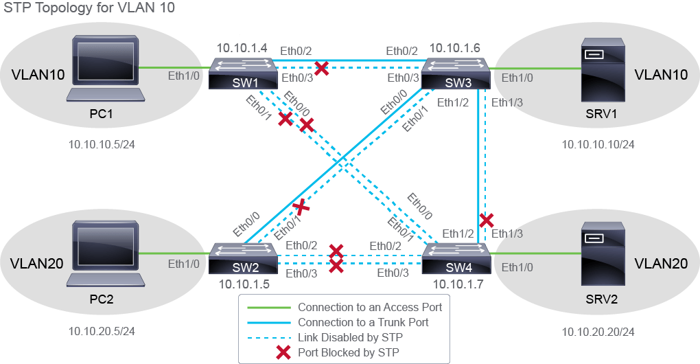
Both Eternet0/2 and 0/3 connect to SW3, but only Ethernet0/2 is forwarding traffic. The STP is blocking Ethernet0/3 to prevent a loop. Only half of the potential bandwidth in this pair of links is in use. Ethernet 0/0 and Ethernet 0/1 interfaces are both in the blocking state. They are not forwarding traffic. All interfaces have STP cost of 100.
Ethernet0/2 與 0/3 都連接到 SW3,但只有 Ethernet0/2 在轉送流量。STP 正在阻斷 Ethernet0/3 以防止迴圈。這對連結中僅有一半的潛在頻寬被使用。Ethernet 0/0 與 Ethernet 0/1 介面都處於阻斷狀態,並未轉送流量。所有介面的 STP 成本都是 100。
To determine the resulting STP topology for VLAN 10, you need to examine the STP information on other switches also.
要判斷 VLAN 10 最終的 STP 拓樸,你也需要檢視其他交換器上的 STP 資訊。
To identify the root switch in the topology, follow the direction in which the Root port is facing. In this case, the Root port is Etherent0/2 facing toward SW3. On SW3, enter the show spanning-tree vlan 10 command.
若要找出拓樸中的根交換器,可依照根埠所指方向追蹤。在此案例中,根埠是朝向 SW3 的 Ethernet0/2。在 SW3 上,輸入 show spanning-tree vlan 10 指令。
SW3# show spanning-tree vlan 10

VLAN0010
  Spanning tree enabled protocol ieee
  Root ID    Priority    24586
             Address     aabb.cc01.2100
     This bridge is the root
             Hello Time   2 sec  Max Age 20 sec  Forward Delay 15 sec

  Bridge ID  Priority    24586  (priority 24576 sys-id-ext 10)
             Address     aabb.cc01.2100
             Hello Time   2 sec  Max Age 20 sec  Forward Delay 15 sec
             Aging Time  300 sec

Interface           Role Sts Cost      Prio.Nbr Type
------------------- ---- --- --------- -------- --------------------------------
Et0/0               Desg FWD 100       128.1    Shr
Et0/1               Desg FWD 100       128.2    Shr
Et0/2               Desg FWD 100       128.3    Shr
Et0/3               Desg FWD 100       128.4    Shr
Et1/0               Desg FWD 100       128.5    Shr
Et1/2               Desg FWD 100       128.7    Shr
Et1/3               Desg FWD 100       128.8    Shr
Notice the previously mentioned This bridge is the root message—you have discovered the root switch. Also notice that none of the interfaces have the Root role, they are all designated ports, which is another indicator that you have discovered the root switch.
請注意先前提到的「本橋接器即為根」訊息,這表示你已找到根交換器。另外也請留意,沒有任何介面具有根埠角色,全部都是指定埠,這也是另一個判斷你已找到根交換器的指標。
After you examine STP information for VLAN 10 on all the switches, the resulting topology should look like the one in the following figure.
在你檢視所有交換器上 VLAN 10 的 STP 資訊之後,最終的拓樸應如下圖所示。
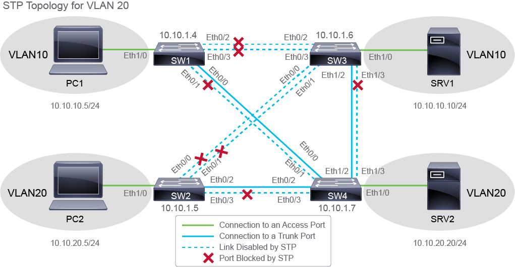
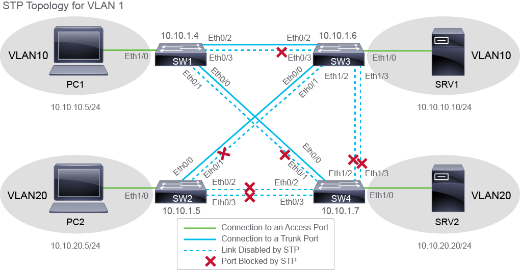
Also, examine the STP configuration for other VLANs and determine the STP topology for VLAN 20 and VLAN 1. For your reference, these two STP topologies are also shown below.
另外,也請檢視其他 VLAN 的 STP 設定,判斷 VLAN 20 與 VLAN 1 的 STP 拓樸。作為參考,這兩個 STP 拓樸也顯示於下方。
To better utilize the links between the SW1 and SW3 switches, you will aggregate them into a Layer 2 EtherChannel link. Start the configuration by shutting down interfaces Ethernet0/2 and Ethernet0/3 on the SW1 switch. Disable both interfaces at the same time.
為了更有效利用 SW1 與 SW3 交換器之間的連結,你將把它們聚合成一條第 2 層 EtherChannel 連結。先在 SW1 交換器上關閉 Ethernet0/2 與 Ethernet0/3 介面,開始進行設定。請同時停用這兩個介面。
On SW1, enter the following commands:
在 SW1 上,輸入以下指令:
SW1# configure terminal
Enter configuration commands, one per line. End with CNTL/Z.
SW1(config)# interface range Ethernet0/2 - 3
SW1(config-if-range)# shutdown
*Dec 28 09:09:31.692: %LINK-5-CHANGED: Interface Ethernet0/2, changed state to administratively down
*Dec 28 09:09:31.693: %LINK-5-CHANGED: Interface Ethernet0/3, changed state to administratively down
*Dec 28 09:09:32.693: %LINEPROTO-5-UPDOWN: Line protocol on Interface Ethernet0/2, changed state to down
*Dec 28 09:09:32.694: %LINEPROTO-5-UPDOWN: Line protocol on Interface Ethernet0/3, changed state to down
Having interfaces disabled while you are configuring them ensures that the incomplete configuration will not create activity on the link.
在設定過程中停用介面,可確保不完整的設定不會在連結上產生活動。
Shut down interfaces Ethernet0/2 and Ethernet0/3 on switch SW3.
在 SW3 交換器上關閉 Ethernet0/2 與 Ethernet0/3 介面。
On SW3, enter the following commands:
在 SW3 上,輸入以下指令:
SW3# configure terminal
Enter configuration commands, one per line. End with CNTL/Z.
SW3(config)# interface range Ethernet0/2 - 3
SW3(config-if-range)# shutdown
*Dec 28 09:10:17.356: %LINK-5-CHANGED: Interface Ethernet0/2, changed state to administratively down
*Dec 28 09:10:17.356: %LINK-5-CHANGED: Interface Ethernet0/3, changed state to administratively down
SW3(config-if-range)#
*Dec 28 09:10:18.360: %LINEPROTO-5-UPDOWN: Line protocol on Interface Ethernet0/2, changed state to down
*Dec 28 09:10:18.360: %LINEPROTO-5-UPDOWN: Line protocol on Interface Ethernet0/3, changed state to downOn SW1, bundle Ethernet0/2 and Ethernet 0/3 interfaces to the logical interface port-channel 1. The aggregation should be negotiated by the LACP protocol.
在 SW1 上,將 Ethernet0/2 與 Ethernet 0/3 介面綁定到邏輯介面 port-channel 1。聚合應由 LACP 協定協商。
On SW1, enter the following commands:
在 SW1 上,輸入以下指令:
SW1(config-if-range)# channel-group 1 mode active
Creating a port-channel interface Port-channel 1
SW1(config-if-range)# On SW3, bundle Ethernet0/2 and Ethernet 0/3 to logical interface port channel 1 using the LACP protocol active mode.
在 SW3 上,使用 LACP 協定的主動模式,將 Ethernet0/2 與 Ethernet 0/3 綁定到邏輯介面 port channel 1。
On SW3, enter the following commands:
在 SW3 上,輸入以下指令:
SW3(config-if-range)# channel-group 1 mode active
Creating a port-channel interface Port-channel 1SW3(config-if-range)#
Note that you have configured both sides of the links to be in the LACP active state, which means to actively negotiate link aggregation. For successful aggregation, it would be enough to have only one side operating in the LACP active mode; the other could be configured to be in passive mode.
請注意,你已將兩側的連結都設定為 LACP 主動狀態,表示雙方都會主動協商鏈路聚合。要成功聚合,其實只要一側設為 LACP 主動模式即可,另一側可設定為被動模式。
Ethernet 0/2 and Ethernet 0/3 interfaces on both switches have a matching configuration regarding the following: speed and duplex attributes, switchport mode set to trunk, native VLAN, and all allowed VLANs on the trunk. Thus, the preconditions for successful establishment of the EtherChannel link are fulfilled. You can enable interfaces Ethernet0/2 and Ethernet0/3 on switch SW1.
兩台交換器上的 Ethernet 0/2 與 Ethernet 0/3 介面,在速度與雙工屬性、switchport 模式設為 trunk、原生 VLAN,以及中繼上允許的所有 VLAN 等方面均相符。因此,成功建立 EtherChannel 連結的先決條件已滿足。你可以在 SW1 交換器上啟用 Ethernet0/2 與 Ethernet0/3 介面。
On SW1, enter the following commands:
在 SW1 上,輸入以下指令:
SW1(config-if-range)# no shutdownEnable interfaces Ethernet0/2 and Ethernet0/3 on switch SW3.
在 SW3 交換器上啟用 Ethernet0/2 與 Ethernet0/3 介面。
On SW3, enter the following commands:
在 SW3 上,輸入以下指令:
SW3(config-if-range)# no shutdown
*Dec 28 09:13:11.268: %LINK-3-UPDOWN: Interface Ethernet0/2, changed state to up
*Dec 28 09:13:11.268: %LINK-3-UPDOWN: Interface Ethernet0/3, changed state to up
*Dec 28 09:13:12.272: %LINEPROTO-5-UPDOWN: Line protocol on Interface Ethernet0/2, changed state to up
*Dec 28 09:13:12.272: %LINEPROTO-5-UPDOWN: Line protocol on Interface Ethernet0/3, changed state to up
SW3(config-if-range)#
*Dec 28 09:13:18.543: %LINEPROTO-5-UPDOWN: Line protocol on Interface Port-channel1, changed state to up
Line protocol for physical interfaces Ethernet 0/2 and Ethernet 0/3 changes state to up. Logical interface port channel 1 also transitions to the up state.
實體介面 Ethernet 0/2 與 Ethernet 0/3 的線路協定狀態轉為 up。邏輯介面 port channel 1 也隨之轉為 up 狀態。
Add the description EChannel to SW3 to port channel 1 interface on SW1 switch.
在 SW1 交換器的 port channel 1 介面上新增描述 description EChannel to SW3。
On SW1, enter the following commands:
在 SW1 上,輸入以下指令:
SW1(config-if-range)# exit
SW1(config)# interface port-channel 1
SW1(config-if)# description EChannel to SW3
SW1(config-if)# end
SW1#Add the description EChannel to SW1 to port channel 1 interface on SW3 switch.
在 SW3 交換器的 port channel 1 介面上新增描述 description EChannel to SW1。
On SW3, enter the following commands:
在 SW3 上,輸入以下指令:
SW3(config-if-range)# exit
SW3(config-if)# interface port-channel 1
SW3(config-if)# description EChannel to SW1
SW3(config-if)# end
SW3#Display the interface status summary on SW1.
顯示 SW1 上的介面狀態摘要。
On SW1, enter the following command:
在 SW1 上,輸入以下指令:
SW1# show interfaces status

Port      Name               Status       Vlan       Duplex  Speed Type
Et0/0     Link to SW4        connected    trunk        auto   auto unknown
Et0/1     Link to SW4        connected    trunk        auto   auto unknown
Et0/2     Link to SW3        connected    trunk        auto   auto unknown
Et0/3     Link to SW3        connected    trunk        auto   auto unknown
Et1/0     Link to PC1        connected    10           auto   auto unknown
Et1/1                        disabled     1            auto   auto unknown
Et1/2                        disabled     1            auto   auto unknown
Et1/3                        disabled     1            auto   auto unknown
Po1       EChannel to SW3    connected    trunk        auto   auto
Ethernet0/2 and 0/3 information is still present in the output, like when you first displayed interface statuses. In addition, now Po1 is also listed. The port channel is up on SW1.
Ethernet0/2 與 0/3 的資訊仍如你第一次顯示介面狀態時一樣存在。此外,現在也列出了 Po1。port channel 在 SW1 上已啟動。
Display the interface status summary on SW3.
顯示 SW3 上的介面狀態摘要。
On SW3, enter the following command:
在 SW3 上,輸入以下指令:
SW3# show interfaces status

Port      Name               Status       Vlan       Duplex  Speed Type
Et0/0     Link to SW2        connected    trunk        auto   auto unknown
Et0/1     Link to SW2        connected    trunk        auto   auto unknown
Et0/2     Link to SW1        connected    trunk        auto   auto unknown
Et0/3     Link to SW1        connected    trunk        auto   auto unknown
Et1/0     Link to SRV1       connected    10           auto   auto unknown
Et1/1                         disabled    1            auto   auto unknown
Et1/2     Link to SW4        connected    trunk        auto   auto unknown
Et1/3     Link to SW4        connected    trunk        auto   auto unknown
Po1       EChannel to SW1    connected    trunk        auto   auto
Port Po1 is listed in the output, along with all other SW3 interfaces. The port channel is up on SW3.
輸出中列出了 Po1 連接埠,以及 SW3 的所有其他介面。port channel 在 SW3 上已啟動。
To analyze whether and how the bundling of ports affected the STP topology, display the spanning tree information for VLAN 10 on SW1 again. You should notice changes compared to what you were seeing before the links were aggregated.
為了分析連接埠綁定是否以及如何影響 STP 拓樸,請再次在 SW1 上顯示 VLAN 10 的生成樹資訊。你應該會注意到與連結聚合之前所見到的情況有所不同。
On SW1, enter the following command:
在 SW1 上,輸入以下指令:
SW1# show spanning-tree vlan 10

VLAN0010
  Spanning tree enabled protocol ieee
  Root ID    Priority    24586
             Address     aabb.cc00.0800
             Cost        56
             Port        65 (Port-channel1)
             Hello Time   2 sec  Max Age 20 sec  Forward Delay 15 sec

  Bridge ID  Priority    32778  (priority 32768 sys-id-ext 10)
             Address     aabb.cc00.0500
             Hello Time   2 sec  Max Age 20 sec  Forward Delay 15 sec
             Aging Time  15  sec

Interface           Role Sts Cost      Prio.Nbr Type
------------------- ---- --- --------- -------- --------------------------------
Et0/0               Desg FWD 100       128.1    Shr
Et0/1               Desg FWD 100       128.2    Shr
Et1/0               Desg FWD 100       128.5    Shr
Po1 Root FWD 56 128.65   Shr
If you display spanning tree information quickly enough, you may find interfaces Ethernet0/0 and 0/1 in listening or learning state. If so, repeat the command until all interfaces are in the forwarding state. The cost of the port channel is 56, which is much lower than the cost of 100, assigned to individual interfaces.
如果你夠快顯示生成樹資訊,可能會發現介面 Ethernet0/0 與 0/1 處於偵聽(listening)或學習(learning)狀態。若是如此,請重複執行該指令,直到所有介面都進入轉送(forwarding)狀態為止。port channel 的成本是 56,遠低於個別介面的成本 100。
Ethernet0/2 and 0/3 are no longer visible to the spanning tree. Instead, they have been replaced by the logical port channel 1 interface. The port channel is in the forwarding state. The forwarding state implies that the port channel is forwarding on all member interfaces. The cost of the port channel is 56, which is much lower than the cost of 100, assigned to individual interfaces. The following figure shows the STP topology for VLAN 10, after the link aggregation.
Ethernet0/2 與 0/3 在生成樹中已不再可見,取而代之的是邏輯介面 port channel 1。該 port channel 處於轉送狀態,這代表 port channel 會在所有成員介面上進行轉送。port channel 的成本是 56,遠低於個別介面的成本 100。下圖顯示鏈路聚合後 VLAN 10 的 STP 拓樸。
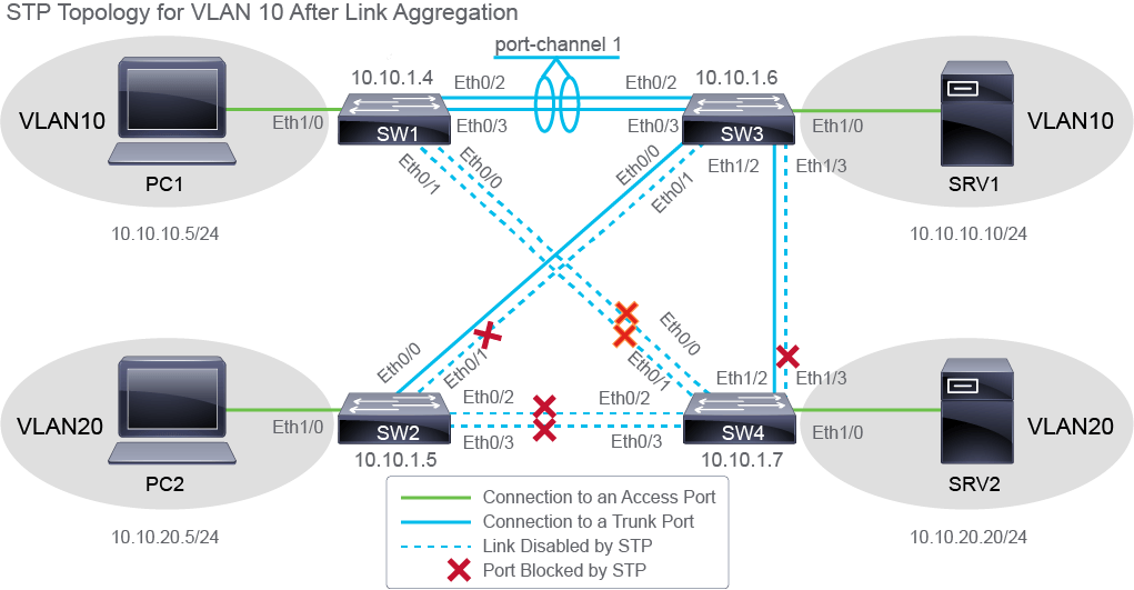
The Ethernet0/0 and Ethernet 0/1 are not in the blocking state any more. They are now forwarding. These interfaces connect to SW4. Since the path from SW1 back to the root (SW3) now costs less due to the port channel establishment, its ports have been selected as the designated ports for these two links. However, the ports on SW4 side of the links are now in the blocking state, which you can verify by issuing the show spanning-tree vlan 10 command on SW4:
Ethernet0/0 與 Ethernet 0/1 不再處於阻斷狀態,而是開始轉送。這些介面連接到 SW4。由於建立 port channel 後,從 SW1 回到根交換器(SW3)的路徑成本降低,因此其連接埠已被選為這兩條連結的指定埠。然而,連結在 SW4 那一側的連接埠現在處於阻斷狀態,你可以在 SW4 上執行 show spanning-tree vlan 10 指令加以驗證:
SW4# show spanning-tree vlan 10

VLAN0010
  Spanning tree enabled protocol ieee
  Root ID    Priority    24586
             Address     aabb.cc01.2100
             Cost        100
             Port        7 (Ethernet1/2)
             Hello Time   2 sec  Max Age 20 sec  Forward Delay 15 sec

  Bridge ID  Priority    28682  (priority 28672 sys-id-ext 10)
             Address     aabb.cc01.2200
             Hello Time   2 sec  Max Age 20 sec  Forward Delay 15 sec
             Aging Time  300 sec

Interface           Role Sts Cost      Prio.Nbr Type
------------------- ---- --- --------- -------- --------------------------------
Et0/0               Altn BLK 100       128.1    Shr
Et0/1               Altn BLK 100       128.2    Shr
Et0/2               Desg FWD 100       128.3    Shr
Et0/3               Desg FWD 100       128.4    Shr
Et1/2               Root FWD 100       128.7    Shr
Et1/3               Altn BLK 100       128.8    Shr
Note that aggregating links does not affect STP root switch selection. The root selection is based on the switch STP priority and its MAC address.
請注意,聚合連結並不會影響 STP 根交換器的選擇。根交換器的選擇是根據交換器的 STP 優先權及其 MAC 位址決定的。
Now that you have successfully configured link aggregation, verify the configuration by displaying the interface information of the port channel 1 interface on SW1.
既然你已成功設定鏈路聚合,請透過顯示 SW1 上 port channel 1 介面的介面資訊來驗證設定。
On SW1, enter the following command:
在 SW1 上,輸入以下指令:
SW1# show interfaces Port-channel 1
Port-channel1 is up, line protocol is up (connected)
  Hardware is Ethernet, address is aabb.cc00.0530 (bia aabb.cc00.0530)
  Description: EChannel to SW3
  MTU 1500 bytes, BW 20000 Kbit/sec, DLY 1000 usec,
     reliability 255/255, txload 1/255, rxload 1/255
  Encapsulation ARPA, loopback not set
  Keepalive set (10 sec)
  Auto-duplex, Auto-speed, media type is unknown
  input flow-control is off, output flow-control is unsupported
 Members in this channel: Et0/2 Et0/3
  ARP type: ARPA, ARP Timeout 04:00:00
  Last input 00:00:00, output never, output hang never
  Last clearing of "show interface" counters never
  Input queue: 0/2000/0/0 (size/max/drops/flushes); Total output drops: 0
  Queueing strategy: fifo
  Output queue: 0/40 (size/max)
  5 minute input rate 0 bits/sec, 0 packets/sec
  5 minute output rate 0 bits/sec, 0 packets/sec
     2041 packets input, 162930 bytes, 0 no buffer
     Received 1858 broadcasts (0 multicasts)
     0 runts, 0 giants, 0 throttles
     0 input errors, 0 CRC, 0 frame, 0 overrun, 0 ignored
     0 input packets with dribble condition detected
     2069 packets output, 158394 bytes, 0 underruns
     0 output errors, 0 collisions, 0 interface resets
     0 unknown protocol drops
     0 babbles, 0 late collision, 0 deferred
     0 lost carrier, 0 no carrier
     0 output buffer failures, 0 output buffers swapped out
From the output, you can determine that the port channel 1 bundles Ethernet0/2 and Ethernet 0/3 interfaces, and that the logical bandwidth of the aggregated link is 20 Mbps (20000 Kbit/s), twice the bandwidth of the individual interfaces.
從輸出中可以判斷,port channel 1 綁定了 Ethernet0/2 與 Ethernet 0/3 介面,且聚合連結的邏輯頻寬為 20 Mbps(20000 Kbit/s),是個別介面頻寬的兩倍。
To view aggregation details, such as aggregation method and how long the aggregated link has been up, display the detailed EtherChannel information on SW1.
若要檢視聚合詳細資訊,例如聚合方法以及聚合連結已啟動多久,請在 SW1 上顯示詳細的 EtherChannel 資訊。
On SW1, enter the following command:
在 SW1 上,輸入以下指令:
SW1# show etherchannel port-channel
                Channel-group listing:
                ----------------------

Group: 1
----------
                Port-channels in the group:
                ---------------------------

Port-channel: Po1    (Primary Aggregator)

------------

Age of the Port-channel   = 0d:01h:11m:56s
Logical slot/port   = 16/0          Number of ports = 2
HotStandBy port = null
Port state          = Port-channel Ag-Inuse
Protocol            =   LACP
Port security       = Disabled

Ports in the Port-channel:

Index   Load   Port     EC state        No of bits
------+------+------+------------------+-----------
  0     00     Et0/2 Active             0
  0     00     Et0/3 Active             0

Time since last port bundled:    0d:01h:11m:39s    Et0/2
From the output, you can determine that the number of ports in this port channel is two. The members are the Ethernet0/2 and Ethernet0/3 interfaces. The protocol that was used to build the bundle is LACP.
從輸出中可以判斷,此 port channel 中的連接埠數量為兩個,成員是 Ethernet0/2 與 Ethernet0/3 介面。用來建立此綁定的協定是 LACP。
View summarized information about the aggregated EtherChannel links on the SW1 switch.
在 SW1 交換器上檢視聚合 EtherChannel 連結的摘要資訊。
On SW1, enter the following command:
在 SW1 上,輸入以下指令:
SW1# show etherchannel summary
Flags:  D - down        P - bundled in port-channel
        I - stand-alone s - suspended
        H - Hot-standby (LACP only)
        R - Layer3      S - Layer2
 U - in use      f - failed to allocate aggregator

        M - not in use, minimum links not met
        u - unsuitable for bundling
        w - waiting to be aggregated
        d - default port


Number of channel-groups in use: 1
Number of aggregators:           1

Group  Port-channel  Protocol    Ports
------+-------------+-----------+-----------------------------------------------
1      Po1(SU)         LACP      Et0/2(P)    Et0/3(P)
The EtherChannel information is shown in one line, and includes EtherChannel type, status of the port channel interface and its member interfaces, and aggregation method. From the output, you can determine that the Layer 2 port channel 1 is operational (indicated by SU flags), that it has two member interfaces that are both active in the aggregated link (indicated by the P flag), and that aggregation was performed using LACP.
EtherChannel 資訊以一行顯示,包括 EtherChannel 類型、port channel 介面及其成員介面的狀態,以及聚合方法。從輸出中可以判斷,第 2 層 port channel 1 正在運作(以 SU 旗標表示),它有兩個成員介面,且都在聚合連結中處於作用中狀態(以 P 旗標表示),聚合是透過 LACP 完成的。
You have successfully configured and verified Layer 2 EtherChannel between the SW1 and SW3 switches.
你已成功在 SW1 與 SW3 交換器之間設定並驗證第 2 層 EtherChannel。
show etherchannel port-channel command that displayed the output as shown below. Which two statements about the EtherChannel are true? (Choose two.) SW1#show etherchannel port-channel< --- output omitted --->
Port-channel: Po1 (Primary Aggregator)
------------
Age of the Port-channel = 0d:01h:11m:56s
Logical slot/port = 16/0 Number of ports = 2
HotStandBy port = null
Port state = Port-channel Ag-Inuse
Protocol = LACP
Port security = Disabled
Ports in the Port-channel:
Index Load Port EC state No of bits
------+------+------+------------------+-----------
0 00 Et0/2 Active 0
0 00 Et0/3 Active 0你執行了
show etherchannel port-channel 指令,顯示了以下輸出。關於此 EtherChannel,下列哪兩項敘述正確?(選擇兩項。) SW1#show etherchannel port-channel< --- output omitted --->
Port-channel: Po1 (Primary Aggregator)
------------
Age of the Port-channel = 0d:01h:11m:56s
Logical slot/port = 16/0 Number of ports = 2
HotStandBy port = null
Port state = Port-channel Ag-Inuse
Protocol = LACP
Port security = Disabled
Ports in the Port-channel:
Index Load Port EC state No of bits
------+------+------+------------------+-----------
0 00 Et0/2 Active 0
0 00 Et0/3 Active 0