Introduction
簡介
This discovery session will let you observe how a switch maintains its MAC address table, which it uses to control the forwarding of frames. The lab is prepared with the devices that are represented in the topology diagram with the IP addresses, as depicted in the table. All devices are fully configured.
本探索實驗會讓您觀察交換器如何維護 MAC 位址表,並利用該表控制框架的轉送。實驗環境已依拓樸圖準備好裝置,其 IP 位址如下表所示。所有裝置皆已完成完整設定。
Topology
拓樸
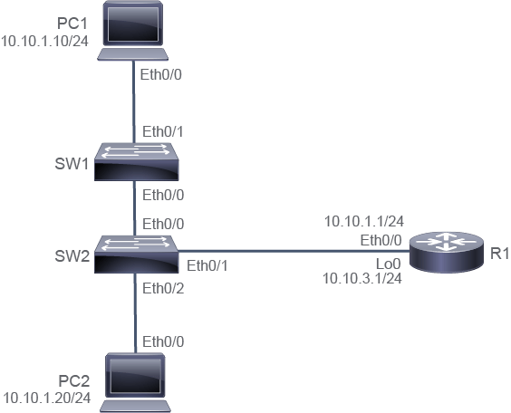
Job Aid
工作輔助資料
Device Information
裝置資訊
Device Information Table
裝置資訊表
Device 裝置 | Characteristic 特性 | Value 值 |
PC1 PC1 | IPv4 address IPv4 位址 | 10.10.1.10/24 10.10.1.10/24 |
PC1 PC1 | Default gateway 預設閘道 | 10.10.1.1 10.10.1.1 |
PC2 PC2 | IPv4 address IPv4 位址 | 10.10.1.20/24 10.10.1.20/24 |
PC2 PC2 | Default gateway 預設閘道 | 10.10.1.1 10.10.1.1 |
SW1 SW1 | VLAN 1 IPv4 address VLAN 1 IPv4 位址 | 10.10.1.2/24 10.10.1.2/24 |
SW1 SW1 | Default gateway 預設閘道 | 10.10.1.1 10.10.1.1 |
SW2 SW2 | VLAN 1 IPv4 address VLAN 1 IPv4 位址 | 10.10.1.3/24 10.10.1.3/24 |
SW2 SW2 | Default gateway 預設閘道 | 10.10.1.1 10.10.1.1 |
R1 R1 | Ethernet0/0 IPv4 address Ethernet0/0 IPv4 位址 | 10.10.1.1/24 10.10.1.1/24 |
R1 R1 | Loopback 0 IPv4 address Loopback 0 IPv4 位址 | 10.10.3.1/24 10.10.3.1/24 |
R1 R1 | Password 密碼 | Cisco123 Cisco123 |
Task 1: Observe How a Switch Operates
任務 1:觀察交換器如何運作
Activity
活動
First, determine the MAC addresses of the Ethernet0/0 interface on PC1, PC2, and R1.
首先,確認 PC1、PC2 與 R1 上 Ethernet0/0 介面的 MAC 位址。
The show interface command displays the MAC address of the interface along with a lot of other information. To reduce the amount of output, allowing you to focus on the line that contains the MAC address, you can pipe the show interface output to include a filter, as shown here.
show interface 指令會顯示介面的 MAC 位址,以及許多其他資訊。為減少輸出內容,讓你能專注於包含 MAC 位址的那一行,你可以把 show interface 的輸出用管線接上 include 過濾器,如下所示。
One at a time, access the console connection to PC1, PC2, and R1 and execute the show interfacecommand.
依序連線至 PC1、PC2 與 R1 的主控台,並執行 show interface指令。
PC1# show interface e0/0 | include address
  Hardware is AmdP2, address is aabb.cc00.7600 (bia aabb.cc00.7600)
  Internet address is 10.10.1.10/24
PC2# show interface e0/0 | include address
Hardware is AmdP2, address is aabb.cc00.7700 (bia aabb.cc00.7700)
Internet address is 10.10.1.20/24R1# show interface e0/0 | include address
Hardware is AmdP2, address is aabb.cc00.7500 (bia aabb.cc00.7500)
Internet address is 10.10.1.1/24In the emulated environment of the lab, the MAC addresses are similar to each other. This similarity will make it easy to distinguish them as the steps of this discovery progress.
在此實驗的模擬環境中,MAC 位址彼此相似。這種相似性能讓您在進行本探索的各個步驟時,更容易辨識它們。
Access the console of SW2, and enter the show mac address-table command.
連線至 SW2 的主控台,並輸入 show mac address-table 指令。
On SW2, enter the following command:
在 SW2 上,輸入以下指令:
SW2# show mac address-table
          Mac Address Table
-------------------------------------------

Vlan    Mac Address       Type        Ports
----    -----------       --------    -----
   1    aabb.cc00.7500    DYNAMIC     Et0/1
   1    aabb.cc00.7700    DYNAMIC     Et0/2
Total Mac Addresses for this criterion: 2
This output is consistent with the information from the Job Aid table. The MAC address that is associated with PC2 is seen on interface Ethernet0/2, and the MAC address that is associated with R1 is associated with interface Ethernet0/1.
此輸出結果與工作輔助資料表中的資訊一致。與 PC2 相關聯的 MAC 位址出現在 Ethernet0/2 介面上,而與 R1 相關聯的 MAC 位址則與 Ethernet0/1 介面相關聯。
PC2 and R1 are both directly connected to SW2 and forward frames very regularly. It is expected that their addresses will remain in the MAC address table almost constantly. You may also see the MAC address of PC1 in the table as well.
PC2 與 R1 都直接連接至 SW2,並經常轉送框架。因此,它們的位址預期會幾乎持續留在 MAC 位址表中。您也可能會在表中看到 PC1 的 MAC 位址。
In this step, be prepared to press Up Arrow to use the Cisco IOS command recall feature to quickly repeat the show mac address-table command after clearing the MAC address table. After clearing the MAC address table, you should find that the MAC address for PC2 and R1 (which are directly connected to SW2) will repopulate themselves quickly.
在此步驟中,請準備好按下 向上鍵 以使用 Cisco IOS 指令回顧功能,在清除 MAC 位址表後快速重複執行 show mac address-table 指令。清除 MAC 位址表後,您應該會發現 PC2 與 R1(直接連接至 SW2)的 MAC 位址會很快重新填入。
On SW2, type the clear mac address-table dynamic command to clear the MAC address table and use command recall to repeatedly execute the show mac address-table command until both addresses are populated. On SW2, enter the following commands:
在 SW2 上,輸入 clear mac address-table dynamic 指令以清除 MAC 位址表,並使用指令回顧功能重複執行 show mac address-table 指令,直到兩個位址都已填入。在 SW2 上,輸入以下指令:
SW2# clear mac address-table dynamic
SW2# show mac address-table
          Mac Address Table
-------------------------------------------

Vlan    Mac Address       Type        Ports
----    -----------       --------    -----
   1    aabb.cc00.7500    DYNAMIC     Et0/1
   1    aabb.cc00.7700    DYNAMIC     Et0/2
Total Mac Addresses for this criterion: 2
If you execute the show mac address-table command very quickly, it might happen that the MAC address table will not be populated yet. In this case, execute the command again, until the table is populated.
如果您非常快速地執行 show mac address-table 指令,MAC 位址表可能尚未填入。在這種情況下,請再次執行該指令,直到表格已填入為止。
The directly connected systems will populate quickly as they send Ethernet frames to the switch.
直接連接的系統會因為向交換器傳送乙太網路框架而很快被填入。
The MAC address of PC1, which is one hop away, is not in the table yet.
PC1 距離為一個躍點,其 MAC 位址尚未出現在表中。
Repeat a similar process on SW1. Clear the MAC address table and then observe the population of the table.
在 SW1 上重複類似的程序。清除 MAC 位址表,然後觀察表格的填入情形。
The MAC address of PC1 should populate in just a few seconds. On SW1, enter the following commands:
PC1 的 MAC 位址應會在幾秒鐘內填入。在 SW1 上,輸入以下指令:
SW1# clear mac address-table dynamic
SW1# show mac address-table
          Mac Address Table
-------------------------------------------

Vlan    Mac Address       Type        Ports
----    -----------       --------    -----
   1    aabb.cc00.7600    DYNAMIC     Et0/1
Total Mac Addresses for this criterion: 1Generate some traffic from PC1 to R1 and PC2. This traffic will have to travel across both SW1 and SW2. Because the MAC address of PC1 is not known to SW2 and the MAC addresses of R1 or PC2 are not known to SW1, there will be flooding of initial Ethernet frames. The flooding will occur too quickly to recognize it in the lab. But the final result should be that all three endpoints (PC1, PC2, and R1) appear in the MAC address tables of both switches.
從 PC1 產生一些傳送至 R1 與 PC2 的流量。這些流量必須經過 SW1 與 SW2。由於 SW2 不知道 PC1 的 MAC 位址,SW1 也不知道 R1 或 PC2 的 MAC 位址,因此最初的乙太網路框架會發生泛洪。這種泛洪發生得太快,在實驗中不易察覺。但最終結果應是所有三個端點(PC1、PC2 與 R1)都出現在兩台交換器的 MAC 位址表中。
Access the console of PC1 and ping R1.
連線至 PC1 的主控台並 ping R1。
PC1# ping 10.10.1.1
Type escape sequence to abort.
Sending 5, 100-byte ICMP Echos to 10.10.1.1, timeout is 2 seconds:
!!!!!
Success rate is 100 percent (5/5), round-trip min/avg/max = 1/1/1 ms
Access the console of PC1 and ping PC2.
連線至 PC1 的主控台並 ping PC2。
PC1# ping 10.10.1.20
Type escape sequence to abort.
Sending 5, 100-byte ICMP Echos to 10.10.1.20, timeout is 2 seconds:
.!!!!
Success rate is 80 percent (4/5), round-trip min/avg/max = 1/2/5 msAccess the console of SW1 and execute the show mac address-tablecommand. Repeat the same on SW2.
存取 SW1 的主控台並執行 show mac address-table指令。在 SW2 上重複相同操作。
On SW1, enter the following command:
在 SW1 上,輸入以下指令:
SW1# show mac address-table
          Mac Address Table
-------------------------------------------

Vlan    Mac Address       Type        Ports
----    -----------       --------    -----
   1    aabb.cc00.7500    DYNAMIC     Et0/0
   1    aabb.cc00.7600    DYNAMIC     Et0/1
   1    aabb.cc00.7700    DYNAMIC     Et0/0
Total Mac Addresses for this criterion: 3
On SW2, enter the following command.
在 SW2 上,輸入以下指令。
SW2# show mac address-table
          Mac Address Table
-------------------------------------------

Vlan    Mac Address       Type        Ports
----    -----------       --------    -----
   1    aabb.cc00.7500    DYNAMIC     Et0/1
   1    aabb.cc00.7600    DYNAMIC     Et0/0
   1    aabb.cc00.7700    DYNAMIC     Et0/2
Total Mac Addresses for this criterion: 3
In the MAC address table of SW1, the MAC addresses of PC2 and R1 are both associated with the Ethernet0/0 interface. Interface Ethernet0/0 is the link to SW2. Any Ethernet frames that are destined for either of these MAC addresses must be forwarded to SW2 for delivery.
在 SW1 的 MAC 位址表中,PC2 與 R1 的 MAC 位址都與 Ethernet0/0 介面相關聯。Ethernet0/0 介面是連接 SW2 的鏈路。任何以這兩個 MAC 位址為目的地的乙太網路框架,都必須轉送至 SW2 才能送達。
In the MAC address table of SW2, the MAC address of PC1 is associated with the Ethernet0/0 interface. Interface Ethernet0/0 is the link to SW1. Any Ethernet frames that are destined for this MAC address must be forwarded to SW1 for delivery.
在 SW2 的 MAC 位址表中,PC1 的 MAC 位址與 Ethernet0/0 介面相關聯。Ethernet0/0 介面是連接 SW1 的鏈路。任何以此 MAC 位址為目的地的乙太網路框架,都必須轉送至 SW1 才能送達。