Inter-VLAN routing is a process of forwarding network traffic from one VLAN to another VLAN using a Layer 3 device.
VLAN 間路由(inter-VLAN routing)是使用第 3 層裝置,將網路流量從一個 VLAN 轉送到另一個 VLAN 的程序。
Option 1: Router with a Separate Interface in Each VLAN
選項 1:路由器在每個 VLAN 中使用獨立介面
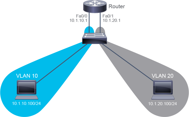
Traditional inter-VLAN routing requires multiple physical interfaces on both the router and the switch. VLANs are associated with unique IP subnets on the network. This subnet configuration facilitates the routing process in a multi-VLAN environment. When you use a router to facilitate inter-VLAN routing, the router interfaces are connected to switch interfaces that are in separate VLANs. Devices on these VLANs send traffic through the router to reach other VLANs. However, when you use a separate interface for each VLAN on a router, you can quickly run out of interfaces. This solution is not very scalable.
傳統的 VLAN 間路由需要路由器與交換器上都有多個實體介面。VLAN 會對應到網路上唯一的 IP 子網路,這種子網路配置有助於在多 VLAN 環境中進行路由。當你使用路由器來實現 VLAN 間路由時,路由器介面會連接到位於不同 VLAN 的交換器介面。這些 VLAN 上的裝置會透過路由器傳送流量以到達其他 VLAN。然而,若每個 VLAN 都在路由器上使用獨立介面,介面數量很快就會用盡,這種做法的可擴充性並不高。
Option 2: Router on a Stick
選項 2:單臂路由(router on a stick)
Not all inter-VLAN routing configurations require multiple physical interfaces. Some router software permits configuring router interfaces as trunk links. Trunk links open up new possibilities for inter-VLAN routing. A router on a stick is a type of router configuration in which a single physical interface routes traffic among multiple VLANs on a network.
並非所有的 VLAN 間路由設定都需要多個實體介面。部分路由器軟體允許將路由器介面設定為中繼鏈路(trunk link)。中繼鏈路為 VLAN 間路由帶來新的可能性。單臂路由是一種路由器設定方式,透過單一實體介面在網路上的多個 VLAN 之間進行路由。
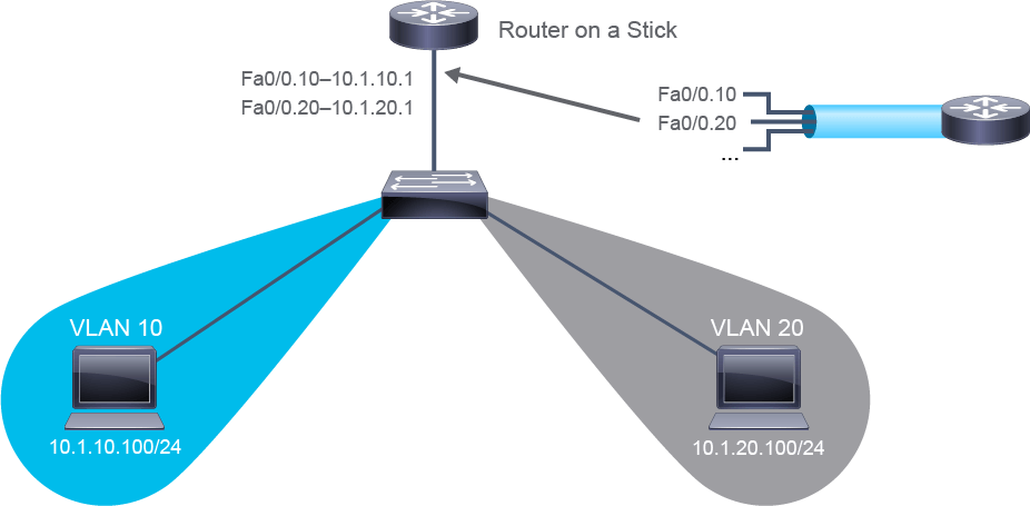
The figure shows a router that is attached to a switch. The router interface is configured to operate as a trunk link and is connected to a switch port that is configured as a trunk. The router performs inter-VLAN routing by accepting VLAN-tagged traffic on the trunk interface coming from the adjacent switch and internally routing between the VLANs using subinterfaces. Subinterfaces are multiple virtual interfaces that are associated with one physical interface. To perform inter-VLAN routing functions, the router must know how to reach all VLANs that are being interconnected; there must be a separate logical connection on the router for each VLAN. VLAN trunking (such as IEEE 802.1Q) must be enabled on these connections.
圖中顯示一台連接到交換器的路由器。路由器介面被設定為以中繼鏈路方式運作,並連接到設定為中繼的交換器連接埠。路由器透過接受來自相鄰交換器、經 VLAN 標記的流量,並使用子介面(subinterface)在 VLAN 之間進行內部路由,藉此執行 VLAN 間路由。子介面是與同一個實體介面關聯的多個虛擬介面。若要執行 VLAN 間路由功能,路由器必須知道如何抵達所有互連的 VLAN;路由器上每個 VLAN 都必須有各自的邏輯連線。這些連線上必須啟用 VLAN 中繼(例如 IEEE 802.1Q)。
These subinterfaces are configured in software. Each is independently configured with its own IP addresses and VLAN assignment. The router routes packets incoming from one subinterface and then sends the data on another subinterface by putting it in a VLAN-tagged frame and sending it back out the same physical interface. Devices on the VLANs have their default gateway set to the appropriate router IP address; in this figure, the devices in VLAN 10 will have default gateway set to 10.1.10.1, and the devices in VLAN 20 will have default gateway set to 10.1.20.1.
這些子介面是以軟體方式設定的,每個子介面都有自己獨立的 IP 位址與 VLAN 指派。路由器會將從某個子介面收到的封包進行路由,然後透過將其放入帶有 VLAN 標記的訊框中,從同一個實體介面送出到另一個子介面。VLAN 上的裝置會將預設閘道設為對應的路由器 IP 位址;在此圖中,VLAN 10 的裝置預設閘道會設為 10.1.10.1,VLAN 20 的裝置預設閘道會設為 10.1.20.1。
Router Trunk Link Configuration Example
路由器中繼鏈路設定範例
The following example shows how you can configure a router on a stick, by configuring subinterfaces and trunking on the router:
以下範例說明如何透過在路由器上設定子介面與中繼來實現單臂路由:
Configure subinterfaces and trunking on the router.
在路由器上設定子介面與中繼。

Router(config)# interface GigabitEthernet 0/0.10
Router(config-subif)# encapsulation dot1q 10
Router(config-subif)# ip address 10.1.10.1 255.255.255.0
Router(config-subif)# interface GigabitEthernet 0/0.20
Router(config-subif)# encapsulation dot1q 20
Router(config-subif)# ip address 10.1.20.1 255.255.255.0The commands used on the router are as follows:
路由器上使用的指令如下:
Command and Variable 指令與變數 | Description 說明 |
interface interface | subinterfaceinterface interface | subinterface | Enters interface or subinterface configuration mode 進入介面或子介面設定模式 |
encapsulation dot1qvlan_numberencapsulation dot1qvlan_number | Defines the encapsulation format as IEEE 802.1Q and specifies the VLAN identifier 將封裝格式定義為 IEEE 802.1Q,並指定 VLAN 識別碼 |
ip addressip_address network_maskip addressip_address network_mask | Assigns an IPv4 address and network mask to an interface 為介面指派 IPv4 位址與網路遮罩 |
In the figure, the GigabitEthernet0/0 interface is divided into two subinterfaces—GigabitEthernet0/0.10 and GigabitEthernet0/0.20. Each subinterface represents the router in each of the VLANs for which it routes.
在圖中,GigabitEthernet0/0 介面被分割為兩個子介面──GigabitEthernet0/0.10 與 GigabitEthernet0/0.20。每個子介面代表路由器在其所路由的各個 VLAN 中的存在。
In the example, the encapsulation dot1q 20 command enables 802.1Q encapsulation trunking on the GigabitEthernet0/0.20 subinterface. The value 20 represents the VLAN number (or VLAN identifier), therefore associating 802.1Q-tagged traffic from this VLAN with the subinterface.
在此範例中,encapsulation dot1q 20 指令在 GigabitEthernet0/0.20 子介面上啟用了 802.1Q 封裝中繼。數值 20 代表 VLAN 編號(或 VLAN 識別碼),因此將此 VLAN 帶有 802.1Q 標記的流量與該子介面關聯起來。
Each 802.1Q-tagged VLAN on the trunk link requires a subinterface with 802.1Q encapsulation trunking that is enabled in this manner. The subinterface number does not have to be the same as the dot1q VLAN number. However, management and troubleshooting are easier when the two numbers are the same.
中繼鏈路上每個帶有 802.1Q 標記的 VLAN 都需要一個以此方式啟用 802.1Q 封裝中繼的子介面。子介面編號不必與 dot1q VLAN 編號相同,但兩者相同時管理與疑難排解會較容易。
In this example, devices in different VLANs use the subinterfaces of the router as default gateways to access the devices that are connected to the other VLANs.
在此範例中,不同 VLAN 中的裝置會使用路由器的子介面作為預設閘道,以存取連接到其他 VLAN 的裝置。
On the switch, assign ports to specific VLANs and configure the port toward the router as a trunk. The trunk link will carry traffic from different VLANs, and the router will route between these VLANs.
在交換器上,將連接埠指派給特定 VLAN,並將朝向路由器的連接埠設定為中繼。此中繼鏈路會承載來自不同 VLAN 的流量,而路由器則在這些 VLAN 之間進行路由。
On the switch, assign ports to specific VLANs and configure the port toward the router as a trunk.
在交換器上,將連接埠指派給特定 VLAN,並將朝向路由器的連接埠設定為中繼。

Switch(config)# interface FastEthernet 0/13
Switch(config-if)# switchport mode trunk
Switch(config-if)# interface FastEthernet 0/1
Switch(config-if)# switchport mode access
Switch(config-if)# switchport access vlan 10
Switch(config-if)# interface FastEthernet 0/3
Switch(config-if)# switchport mode access
Switch(config-if)# switchport access vlan 20The commands used on the switch are as follows:
交換器上使用的指令如下:
Command and Variable 指令與變數 | Description 說明 |
interface interfaceinterface interface | Enters interface configuration mode. 進入介面設定模式。 |
switchport mode trunkswitchport mode trunk | Sets the interface to trunk mode. 將介面設為中繼模式。 |
switchport mode accessswitchport mode access | Sets the interface to access mode. 將介面設為存取模式。 |
switchport accessvlan_numberswitchport accessvlan_number | Sets the access VLAN when the interface is in the access mode. To reset the access-mode VLAN to the appropriate default VLAN for the switch, use the no form of this command.在介面處於存取模式時設定存取 VLAN。若要將存取模式 VLAN 重設為交換器適用的預設 VLAN,請使用此指令的 no 形式。 |
Verify VLAN Subinterfaces
驗證 VLAN 子介面
To verify the router configuration, use the show commands to display the VLANs and IP routing information for each VLAN to verify that the routing table includes the subnets of all VLANs.
若要驗證路由器設定,可使用 show 指令顯示每個 VLAN 的 VLAN 與 IP 路由資訊,以確認路由表中包含所有 VLAN 的子網路。
The sample output shows two VLAN subinterfaces—GigabitEthernet0/0.10 and GigabitEthernet0/0.20.
此範例輸出顯示兩個 VLAN 子介面──GigabitEthernet0/0.10 與 GigabitEthernet0/0.20。
The show ip route command displays the state of the routing table. The sample output shows two subinterfaces. The GigabitEthernet0/0.10 and GigabitEthernet0/0.20 VLAN subinterfaces are directly connected to the router.
show ip route 指令會顯示路由表的狀態。範例輸出顯示了兩個子介面。GigabitEthernet0/0.10 與 GigabitEthernet0/0.20 這兩個 VLAN 子介面都與路由器直接連接。
Option 3: Layer 3 Switch
選項 3:第 3 層交換器
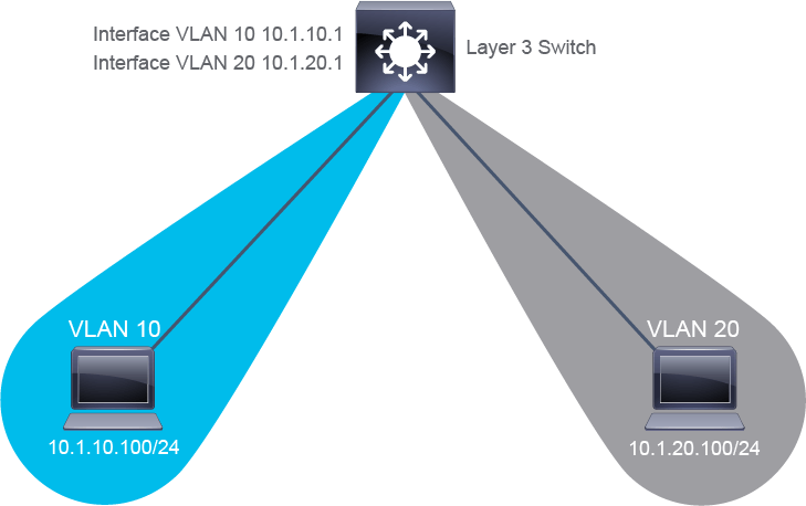
Some switches can perform Layer 3 functions, replacing the need for dedicated routers to perform basic routing on a network. Layer 3 switches are capable of performing inter-VLAN routing. Traditionally, a switch makes forwarding decisions by looking at the Layer 2 header, whereas a router makes forwarding decisions by looking at the Layer 3 header. A Layer 3 switch combines the functionality of a switch and a router in one device. It switches traffic when the source and destination are in the same VLAN and routes traffic when the source and destination are in different VLANs (that is, on different IP subnets). To enable a Layer 3 switch to perform routing functions, you must properly configure VLAN interfaces on the switch; these are called switch virtual interfaces (SVIs). You must use the IP addresses that match the subnet that the VLAN is associated with on the network. The Layer 3 switch must also have IP routing enabled. Devices on the VLANs have their default gateway set to the appropriate Layer 3 switch IP address.
部分交換器可以執行第 3 層功能,取代由專用路由器在網路上執行基本路由的需求。第 3 層交換器能夠執行 VLAN 間路由。傳統上,交換器透過檢視第 2 層標頭來做出轉送決策,而路由器則是透過檢視第 3 層標頭來做出轉送決策。第 3 層交換器將交換器與路由器的功能結合在單一裝置中:當來源與目的位於同一個 VLAN 時進行交換,當來源與目的位於不同 VLAN(也就是不同的 IP 子網路)時則進行路由。若要讓第 3 層交換器執行路由功能,必須在交換器上正確設定 VLAN 介面,這稱為交換器虛擬介面(switch virtual interface,SVI)。你必須使用與網路上該 VLAN 所對應子網路相符的 IP 位址,且第 3 層交換器也必須啟用 IP 路由功能。VLAN 上的裝置會將預設閘道設為對應的第 3 層交換器 IP 位址。
Layer 3 switching is more scalable than router on a stick because the latter can pass only so much traffic through the trunk link. In general, a Layer 3 switch is primarily a Layer 2 device that has been upgraded to have some routing capabilities. A router is a Layer 3 device that can perform some switching functions. Layer 3 switches do not have WAN interfaces, while routers do. Typically, routers also support more advanced Layer 3 features (for example, Network Address Translation, encryption, and tunneling) than Layer 3 switches.
第 3 層交換比單臂路由更具擴充性,因為單臂路由的中繼鏈路能承載的流量有限。一般而言,第 3 層交換器主要是一台升級後具備部分路由能力的第 2 層裝置;路由器則是一台第 3 層裝置,能執行部分交換功能。第 3 層交換器沒有 WAN 介面,而路由器則有。通常路由器也比第 3 層交換器支援更多進階的第 3 層功能(例如網路位址轉換、加密與通道技術)。
However, the line between switches and routers becomes hazier every day. Some Layer 2 switches support limited Layer 3 functionality, such as static routing on SVIs, so you can configure static routes, but routing protocols are not supported.
然而,交換器與路由器之間的界線正逐漸模糊。部分第 2 層交換器支援有限的第 3 層功能,例如在 SVI 上進行靜態路由,因此你可以設定靜態路由,但不支援路由協定。
Following is an example configuration on the Layer 3 switch with PCs that are connected to VLAN 10 and VLAN 20. PCs in VLAN 10 will have default gateway 10.1.10.1, and PCs in VLAN 20 will have default gateway 10.1.20.1. The Layer 3 switch will perform routing between VLAN 10 and VLAN 20.
以下是第 3 層交換器上的設定範例,其中 PC 連接到 VLAN 10 與 VLAN 20。VLAN 10 中的 PC 預設閘道為 10.1.10.1,VLAN 20 中的 PC 預設閘道為 10.1.20.1。此第 3 層交換器將在 VLAN 10 與 VLAN 20 之間執行路由。
ip routing
!
interface Vlan10
 ip address 10.1.10.1 255.255.255.0
 no shutdown
!
interface Vlan20
 ip address 10.1.20.1 255.255.255.0
 no shutdown
After having inserted the SVI interfaces configuration, the routing table will look as the following:
完成 SVI 介面設定後,路由表將如下所示:
Router# show ip route
<--- output omitted --->

Gateway of last resort is not set
10.0.0.0/8 is variably subnetted, 2 subnets
C        10.1.10.0/24 is directly connected, Vlan10
L        10.1.10.1/32 is directly connected, Vlan10
C        10.1.20.0/24 is directly connected, Vlan20
L 10.1.20.1/32 is directly connected, Vlan20interface Fastethernet0/0.10
encapsulation dot1q 10
ip address 10.1.10.1 255.255.255.0
no shutdown
!
interface Fastethernet0/0.20
encapsulation dot1q 20
ip address 10.1.20.1 255.255.255.0
no shutdown以下範例中使用的是哪一種 VLAN 間路由解決方案?interface Fastethernet0/0.10
encapsulation dot1q 10
ip address 10.1.10.1 255.255.255.0
no shutdown
!
interface Fastethernet0/0.20
encapsulation dot1q 20
ip address 10.1.20.1 255.255.255.0
no shutdown