Introduction
簡介
In this activity, you will configure IPv6 static routing between R1 and R3 and verify connectivity between end devices in the network. Router R2 has static IPv6 routes preconfigured. Study the topology diagram and address table to understand the network connectivity and addressing. All systems are currently configured with IPv4 addresses and IPv6 addresses. You will define a default route and a floating route on the R1 router.
在本活動中,你將在 R1 與 R3 之間設定 IPv6 靜態路由,並驗證網路中終端裝置之間的連線。R2 路由器已預先設定好 IPv6 靜態路由。請研讀拓樸圖與位址表,以了解網路連線與定址方式。所有系統目前皆已同時設定 IPv4 位址與 IPv6 位址。你將在 R1 路由器上定義一條預設路由與一條浮動路由。
Topology
拓樸
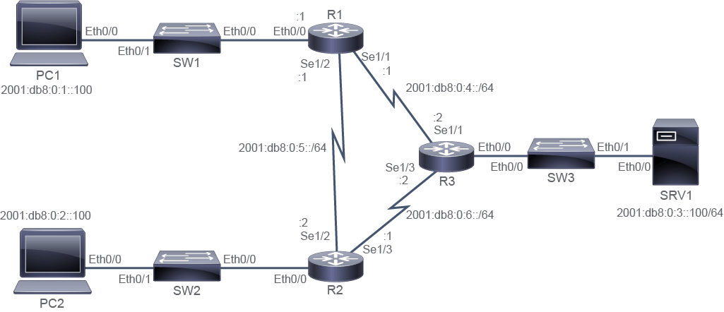
Job Aid
工作輔助資料
Device Information
裝置資訊
Device Information Table
裝置資訊表
Device 裝置 | Characteristic 特性 | Value 值 |
PC1 PC1 | IPv6 address IPv6 位址 | 2001:db8:0:1::100/64 2001:db8:0:1::100/64 |
PC2 PC2 | IPv6 address IPv6 位址 | 2001:db8:0:2::100/64 2001:db8:0:2::100/64 |
SRV1 SRV1 | IPv6 address IPv6 位址 | 2001:db8:0:3::100/64 2001:db8:0:3::100/64 |
R1 R1 | Ethernet0/0 IPv6 address Ethernet0/0 IPv6 位址 | 2001:db8:0:1::1/64 2001:db8:0:1::1/64 |
R1 R1 | Serial1/1 IPv6 address Serial1/1 IPv6 位址 | 2001:db8:0:4::1/64 2001:db8:0:4::1/64 |
R1 R1 | Serial1/2 IPv6 address Serial1/2 IPv6 位址 | 2001:db8:0:5::1/64 2001:db8:0:5::1/64 |
R2 R2 | Ethernet0/0 IPv6 address Ethernet0/0 IPv6 位址 | 2001:db8:0:2::1/64 2001:db8:0:2::1/64 |
R2 R2 | Serial1/2 IPv6 address Serial1/2 IPv6 位址 | 2001:db8:0:5::2/64 2001:db8:0:5::2/64 |
R2 R2 | Serial1/3 IPv6 address Serial1/3 IPv6 位址 | 2001:db8:0:6::1/64 2001:db8:0:6::1/64 |
R3 R3 | Ethernet0/0 IPv6 address Ethernet0/0 IPv6 位址 | 2001:db8:0:3::1/64 2001:db8:0:3::1/64 |
R3 R3 | Serial1/1 IPv6 address Serial1/1 IPv6 位址 | 2001:db8:0:4::2/64 2001:db8:0:4::2/64 |
R3 R3 | Serial1/3 IPv6 address Serial1/3 IPv6 位址 | 2001:db8:0:6::2/64 2001:db8:0:6::2/64 |
Task 1: Configure IPv6 Static Routes
任務 1:設定 IPv6 靜態路由
Activity
活動
SRV1 is configured for remote access using Telnet. However, user at PC1 cannot establish the Telnet connection. From PC1, try accessing the SRV1 server using Telnet.
SRV1 已設定為可透過 Telnet 遠端存取。然而,PC1 的使用者無法建立 Telnet 連線。請從 PC1 嘗試使用 Telnet 存取 SRV1 伺服器。
On PC1, enter these commands:
在 PC1 上,輸入以下指令:
PC1# telnet 2001:db8:0:3::100
Trying 2001:db8:0:3::100 ...
% Connection timed out; remote host not responding
The Telnet connection to SRV1 cannot be established, because the remote host is not responding.
無法建立到 SRV1 的 Telnet 連線,因為遠端主機沒有回應。
Telnet connectivity test failed. Check IPv6 connectivity from PC1 to SRV1 and PC2. Both checks should fail.
Telnet 連線測試失敗。請檢查從 PC1 到 SRV1 與 PC2 的 IPv6 連線,兩項檢查應該都會失敗。
On PC1, enter these commands:
在 PC1 上,輸入以下指令:
PC1# ping 2001:db8:0:3::100
Type escape sequence to abort.
Sending 5, 100-byte ICMP Echos to 2001:DB8:0:3::100, timeout is 2 seconds:
.....
Success rate is 0 percent (0/5)

PC1# ping 2001:db8:0:2::100
Type escape sequence to abort.
Sending 5, 100-byte ICMP Echos to 2001:DB8:0:2::100, timeout is 2 seconds:
.....
Success rate is 0 percent (0/5)
Both pings are failing. In the lab network there is no full IPv6 connectivity.
兩次 ping 皆失敗。在此實驗網路中,尚未有完整的 IPv6 連線。
The IPv6 connectivity checks fail because routers R1 and R3 do not have routing preconfigured. Examine the IPv6 routing table on each router to explore the IPv6 routing information that the routers have in their routing table.
IPv6 連線檢查失敗,是因為路由器 R1 與 R3 尚未預先設定路由。請檢視每台路由器上的 IPv6 路由表,以了解路由器路由表中所擁有的 IPv6 路由資訊。
On R1, enter the following command:
在 R1 上,輸入以下指令:
R1# show ipv6 route
IPv6 Routing Table - default - 7 entries
<--- output omitted --->
C 2001:DB8:0:1::/64 [0/0]
     via Ethernet0/0, directly connected
L   2001:DB8:0:1::1/128 [0/0]
     via Ethernet0/0, receive
C 2001:DB8:0:4::/64 [0/0]
     via Serial1/1, directly connected
L   2001:DB8:0:4::1/128 [0/0]
     via Serial1/1, receive
C 2001:DB8:0:5::/64 [0/0]
     via Serial1/2, directly connected
L   2001:DB8:0:5::1/128 [0/0]
     via Serial1/2, receive
L   FF00::/8 [0/0]
     via Null0, receive
The output shows, that R1 has information about directly connected networks only. Router R1 does not have information about neither SRV1 LAN (2001:db8:0:3::/64) nor PC2 LAN (2001:db8:0:2::/64).
輸出顯示,R1 只擁有直接連接網路的資訊。R1 路由器並未擁有 SRV1 LAN(2001:db8:0:3::/64)或 PC2 LAN(2001:db8:0:2::/64)的資訊。
The sources of the routing table entries are identified by a code at the beginning of the entry which indicates how the route was learned. The 2001:db8:0:1::/64 network is identified with a "C" code, which identifies the directly connected network on the Ethernet0/0 interface. The 2001:db8:0:1::1/128 IPv6 address is identified with a "L" code, which identifies the address assigned to Ethernet0/0 interface, belonging to the 2001:db8:0:1::/64 network. These entries are added to the routing table automatically when router interface is configured, enabled, and active.
路由表項目的來源,是以項目開頭的代碼來識別,該代碼指出此路由是如何得知的。2001:db8:0:1::/64 網路以「C」代碼標示,代表這是 Ethernet0/0 介面上直接連接的網路。2001:db8:0:1::1/128 這個 IPv6 位址則以「L」代碼標示,代表這是指派給 Ethernet0/0 介面、屬於 2001:db8:0:1::/64 網路的位址。當路由器介面設定完成、啟用並處於運作狀態時,這些項目會自動加入路由表中。
On R2, enter the following command:
在 R2 上,輸入以下指令:
R2# show ipv6 route
IPv6 Routing Table - default - 9 entries
<--- output omitted --->
S ::/0 [1/0]
     via 2001:DB8:0:6::2
S 2001:DB8:0:1::/64 [1/0]
     via 2001:DB8:0:5::1
C 2001:DB8:0:2::/64 [0/0]
     via Ethernet0/0, directly connected
L   2001:DB8:0:2::1/128 [0/0]
     via Ethernet0/0, receive
C 2001:DB8:0:5::/64 [0/0]
     via Serial1/2, directly connected
L   2001:DB8:0:5::2/128 [0/0]
     via Serial1/2, receive
C 2001:DB8:0:6::/64 [0/0]
     via Serial1/3, directly connected
L   2001:DB8:0:6::1/128 [0/0]
     via Serial1/3, receive
L   FF00::/8 [0/0]
     via Null0, receive
The output shows that, besides information about directly connected networks, R2 has two static entries. The first static entry is an IPv6 default route indicated by ::/0. The default route points to the R3 router as the next hop (2001:db8:0:6::2). The second static entry is for PC1 LAN (2001:db8:0:1::/64) which is available via R1 router (next-hop IPv6 2001:db8:0:5::1.)
輸出顯示,除了直接連接網路的資訊外,R2 還有兩筆靜態項目。第一筆靜態項目是以 ::/0 表示的 IPv6 預設路由,該預設路由以 R3 路由器(2001:db8:0:6::2)作為下一跳。第二筆靜態項目是 PC1 LAN(2001:db8:0:1::/64),可透過 R1 路由器到達(下一跳 IPv6 位址為 2001:db8:0:5::1)。
On R3, enter the following command:
在 R3 上,輸入以下指令:
R3# show ipv6 route
IPv6 Routing Table - default - 7 entries
<--- output omitted --->
C 2001:DB8:0:3::/64 [0/0]
     via Ethernet0/0, directly connected
L   2001:DB8:0:3::1/128 [0/0]
     via Ethernet0/0, receive
C 2001:DB8:0:4::/64 [0/0]
     via Serial1/1, directly connected
L   2001:DB8:0:4::2/128 [0/0]
     via Serial1/1, receive
C 2001:DB8:0:6::/64 [0/0]
     via Serial1/3, directly connected
L   2001:DB8:0:6::2/128 [0/0]
     via Serial1/3, receive
L   FF00::/8 [0/0]
     via Null0, receive
Based on the output, you see that R3 router knows of its directly connected networks only. It has no information about PC1 and PC2 LANs (2001:db8:0:1::/64 and 2001:db8:0:2::/64).
從輸出中可以看出,R3 路由器僅知道其直接連接的網路,並未擁有 PC1 與 PC2 LAN(2001:db8:0:1::/64 與 2001:db8:0:2::/64)的資訊。
The routing tables content reveals that routing information must be added to R1 and R3 routers. On R1, you need add two static routes, a default IPv6 route, and a static IPv6 route to PC2 LAN which will take care of routing packets from PC1 towards the SRV1 server. To provide the path for the response packets from SRV1 to PC1, you need to add a static IPv6 route towards PC1 LAN on R3. To provide full connectivity, you also need to add a static IPv6 route to PC2 LAN.
路由表的內容顯示,必須在 R1 與 R3 路由器上加入路由資訊。在 R1 上,你需要新增兩條靜態路由:一條 IPv6 預設路由,以及一條指向 PC2 LAN 的 IPv6 靜態路由,以便將封包從 PC1 路由至 SRV1 伺服器。為了讓來自 SRV1、回覆給 PC1 的封包有路徑可走,你需要在 R3 上新增一條指向 PC1 LAN 的靜態 IPv6 路由。為了提供完整連線,你還需要新增一條指向 PC2 LAN 的靜態 IPv6 路由。
You must ensure that the IPv6 routing function is enabled on the router. Otherwise, you would be able to type in the IPv6 routes but the router will not perform IPv6 routing. By default, IPv6 routing is not enabled. You must enable IPv6 routing on both R1 and R3.
你必須確認路由器上已啟用 IPv6 路由功能,否則即使輸入了 IPv6 路由,路由器也不會執行 IPv6 路由。IPv6 路由預設並未啟用,你必須在 R1 與 R3 上都啟用 IPv6 路由。
Enable IPv6 routing on R1 and R3 using the ipv6 unicast-routing command.
使用 ipv6 unicast-routing 指令,在 R1 與 R3 上啟用 IPv6 路由。
On R1, enter the following commands:
在 R1 上,輸入以下指令:
R1# configure terminal
R1(config)# ipv6 unicast-routing
R1(config)#
On R3, enter the following commands:
在 R3 上,輸入以下指令:
R3# configure terminal
R3(config)# ipv6 unicast-routing
R3(config)#Add a default IPv6 route on R1, specifying R3 router as the next-hop.
在 R1 上新增一條 IPv6 預設路由,指定 R3 路由器作為下一跳。
On R1, enter the following command:
在 R1 上,輸入以下指令:
R1(config)# ipv6 route ::/0 2001:db8:0:4::2The default IPv6 route is denoted ::/0. Its IPv4 equivalent is 0.0.0.0/0 quad zero network id. The next hop IPv6 address is the address of the R3 Serial 1/1 interface.
此 IPv6 預設路由以 ::/0 表示,其對應的 IPv4 表示法為 0.0.0.0/0(四零網路 ID)。下一跳 IPv6 位址是 R3 的 Serial 1/1 介面位址。
On R1 router, add a static IPv6 route to 2001:db8:0:2::/64 network.
在 R1 路由器上,新增一條指向 2001:db8:0:2::/64 網路的 IPv6 靜態路由。
On R1, enter the following command:
在 R1 上,輸入以下指令:
R1(config)# ipv6 route 2001:db8:0:2::/64 2001:db8:0:5::2The next-hop IPv6 address belong to Serial 1/2 interface of R2.
下一跳 IPv6 位址屬於 R2 的 Serial 1/2 介面。
Without leaving the global configuration mode, verify that both routes are added to R1 IPv6 routing table. Use the do keyword in front of the show command.
無須離開全域設定模式,即可驗證這兩條路由是否已加入 R1 的 IPv6 路由表。請在 show 指令前加上 do 關鍵字。
On R1, enter the following command:
在 R1 上,輸入以下指令:
R1(config)# do show ipv6 route
IPv6 Routing Table - default - 9 entries
<--- output omitted --->
S   ::/0 [1/0]
     via 2001:DB8:0:4::2
C   2001:DB8:0:1::/64 [0/0]
     via Ethernet0/0, directly connected
L   2001:DB8:0:1::1/128 [0/0]
     via Ethernet0/0, receive
S   2001:DB8:0:2::/64 [1/0]
     via 2001:DB8:0:5::2
C   2001:DB8:0:4::/64 [0/0]
     via Serial1/1, directly connected
L   2001:DB8:0:4::1/128 [0/0]
     via Serial1/1, receive
C   2001:DB8:0:5::/64 [0/0]
     via Serial1/2, directly connected
L   2001:DB8:0:5::1/128 [0/0]
     via Serial1/2, receive
L   FF00::/8 [0/0]
     via Null0, receive
Both routes that you entered are included in the IPv6 routing table. Because of the longest-prefix matching used in routing, packets destined to PC2 LAN will be forwarded via R2 router. Packets destined to other networks will be routed according to the default route entry, via the R3 router.
你剛輸入的兩條路由都已包含在 IPv6 路由表中。由於路由採用最長前綴比對,目的地為 PC2 LAN 的封包將經由 R2 路由器轉送;目的地為其他網路的封包,則會依照預設路由項目經由 R3 路由器轉送。
Note that the routes in IPv6 routing table are sorted from the lowest to the highest number. The same is true of IPv4 routing table.
請注意,IPv6 路由表中的路由是依數值由小到大排序的,IPv4 路由表也是如此。
Since the R2 router is preconfigured, adding a static route to PC2 LAN on R1 now ensures the connectivity in both directions. From PC1, verify the connectivity between PC1 and PC2.
由於 R2 路由器已預先設定完成,因此在 R1 上新增一條指向 PC2 LAN 的靜態路由後,兩個方向的連線便都已就緒。請從 PC1 驗證 PC1 與 PC2 之間的連線。
On PC1, enter this command:
在 PC1 上,輸入以下指令:
PC1# ping 2001:db8:0:2::100
Type escape sequence to abort.
Sending 5, 100-byte ICMP Echos to 2001:DB8:0:3::100, timeout is 2 seconds:
!!!!!
Success rate is 100 percent (5/5), round-trip min/avg/max = 8/15/43 msConfiguring routes on R1 ensured connectivity in one direction, from PC1 to SRV1. To ensure connectivity in both directions for all devices, on R3, add static routes to PC1 LAN and PC2 LAN.
在 R1 上設定路由,已確保從 PC1 到 SRV1 這個方向的連線。為了確保所有裝置在兩個方向上都有連線,請在 R3 上新增指向 PC1 LAN 與 PC2 LAN 的靜態路由。
On R3, enter the following command:
在 R3 上,輸入以下指令:
R3(config)# ipv6 route 2001:db8:0:1::/64 2001:db8:0:4::1
R3(config)# ipv6 route 2001:db8:0:2::/64 2001:db8:0:6::1Without leaving the global configuration mode, verify that both IPv6 static routes are added to R3 IPv6 routing table. Use the do keyword in front of the show command.
無須離開全域設定模式,即可驗證這兩條 IPv6 靜態路由是否已加入 R3 的 IPv6 路由表。請在 show 指令前加上 do 關鍵字。
On R3, enter the following command:
在 R3 上,輸入以下指令:
R3(config)# do show ipv6 route static
IPv6 Routing Table - default - 9 entries
Codes: C - Connected, L - Local, S - Static, U - Per-user Static route
       B - BGP, HA - Home Agent, MR - Mobile Router, R - RIP
       H - NHRP, I1 - ISIS L1, I2 - ISIS L2, IA - ISIS interarea
       IS - ISIS summary, D - EIGRP, EX - EIGRP external, NM - NEMO
       ND - ND Default, NDp - ND Prefix, DCE - Destination, NDr - Redirect
       O - OSPF Intra, OI - OSPF Inter, OE1 - OSPF ext 1, OE2 - OSPF ext 2
       ON1 - OSPF NSSA ext 1, ON2 - OSPF NSSA ext 2, l - LISP
S   2001:DB8:0:1::/64 [1/0]
     via 2001:DB8:0:4::1
S   2001:DB8:0:2::/64 [1/0]
     via 2001:DB8:0:6::1
Both routes that you entered are included in the IPv6 routing table. You can also see the default administrative distance of the static route, which is 1.
你剛輸入的兩條路由都已包含在 IPv6 路由表中。你也可以看到靜態路由的預設管理距離為 1。
Verify IPv6 connectivity between PC1 and SRV1, by using ping and traceroute commands.
使用 ping 與 traceroute 指令,驗證 PC1 與 SRV1 之間的 IPv6 連線。
On PC1, enter the following command:
在 PC1 上,輸入以下指令:
PC1# ping 2001:db8:0:3::100
Type escape sequence to abort.
Sending 5, 100-byte ICMP Echos to 2001:DB8:0:3::100, timeout is 2 seconds:
!!!!!
Success rate is 100 percent (5/5), round-trip min/avg/max = 8/15/43 ms

PC1# traceroute 2001:db8:0:3::100
Type escape sequence to abort.
Tracing the route to 2001:DB8:0:3::100

 1 2001:DB8:0:1::1 0 msec 1 msec 0 msec
 2 2001:DB8:0:4::2 9 msec 9 msec 8 msec
 3 2001:DB8:0:3::100 9 msec 9 msec 9 msec
The successful ping test verifies that there is connectivity between PC1 and SRV1. The traceroute command confirms the connectivity and adds information about the path that IPv6 packets are taking from PC1 to SRV1. Based on the IPv6 addresses shown in the output, you can see that the packets follow the PC1 > R1 > R3 > SRV1 path.
成功的 ping 測試證實 PC1 與 SRV1 之間已有連線。traceroute 指令則進一步確認連線,並提供 IPv6 封包從 PC1 到 SRV1 所經路徑的資訊。根據輸出中顯示的 IPv6 位址,可以看出封包依循 PC1 > R1 > R3 > SRV1 的路徑。
The network topology shows that there is an alternative path to SRV1: PC1 > R1 > R2 > R3 > SRV1. It can serve as a backup path in case of the link failure between R1 and R3. To ensure this backup path is immediately available, configure a floating static default route to SRV1 network via R2. Use administrative distance 200. Exit to the Privileged EXEC mode.
網路拓樸顯示還有一條可到達 SRV1 的替代路徑:PC1 > R1 > R2 > R3 > SRV1,可在 R1 與 R3 之間的鏈路故障時作為備援路徑。為了確保此備援路徑能立即可用,請設定一條經由 R2、指向 SRV1 網路的浮動靜態預設路由,管理距離設為 200。設定完成後請結束並回到特權 EXEC 模式。
On R1, enter the following commands:
在 R1 上,輸入以下指令:
R1(config)# ipv6 route ::/0 2001:db8:0:5::2 200
R1(config)# end
By explicitly specifying the administrative distance, you are changing the default "trustworthiness" of the static route. Setting the administrative distance to 200 makes it unlikely that this route will be installed in the routing table. The maximum value you can set is 254. This is why the route is called floating. It's administrative distance floats high above other administrative distance values making it difficult for the route to "land" in the routing table. The route will get installed only when all sources with lesser administrative distance become unavailable.
藉由明確指定管理距離,你改變了此靜態路由預設的「可信度」。將管理距離設為 200,會使這條路由不容易被安裝到路由表中。可設定的最大值為 254。這也是它被稱為「浮動」路由的原因:它的管理距離高高「漂浮」在其他管理距離值之上,使其難以「落入」路由表中。只有當所有管理距離較低的路由來源都無法使用時,此路由才會被安裝。
Verify that the floating route is not in the IPv6 routing table.
驗證浮動路由並未出現在 IPv6 路由表中。
On R1, enter the following command:
在 R1 上,輸入以下指令:
R1# show ipv6 route static
IPv6 Routing Table - default - 9 entries
<--- output omitted --->
S   ::/0 [1/0]
     via 2001:DB8:0:4::2
S   2001:DB8:0:2::/64 [1/0]
     via 2001:DB8:0:5::2
The IPv6 default route is the same one you configured at the beginning of the lab using R3 as the next hop.
這條 IPv6 預設路由,與你在實驗開始時使用 R3 作為下一跳所設定的路由相同。
To ensure bidirectional connectivity in cases of R1-R3 link failure, you have to add a floating route on R3 router also. The current IPv6 static route to PC1 LAN (2001:db8:0:1::/64) uses R1 router as the next hop. In case of the link failure, the route is going to be removed from the routing table. Configure an alternative floating IPv6 static route to PC1 LAN, using R2 as the next hop. Use administrative distance of 200.
為了在 R1 與 R3 之間的鏈路發生故障時,仍能確保雙向連線,你也必須在 R3 路由器上新增一條浮動路由。目前指向 PC1 LAN(2001:db8:0:1::/64)的 IPv6 靜態路由,以 R1 路由器作為下一跳。若鏈路故障,該路由將從路由表中移除。請設定一條以 R2 作為下一跳、指向 PC1 LAN 的替代浮動 IPv6 靜態路由,管理距離設為 200。
On R3, enter the following command:
在 R3 上,輸入以下指令:
R3(config)# ipv6 route 2001:db8:0:1::/64 2001:db8:0:6::1 200To make sure that the floating route will be installed in the IPv6 routing table, simulate a R1-R3 link failure by manually disabling the Serial 1/1 interface on R1.
為了確認浮動路由確實會被安裝到 IPv6 路由表中,請手動停用 R1 上的 Serial 1/1 介面,以模擬 R1-R3 鏈路故障。
On R1, enter the following command:
在 R1 上,輸入以下指令:
R1# configure terminal
R1(config)# interface Serial 1/1
R1(config-if)# shutdown
R1(config-if)#
*May 30 19:31:33.124: %LINK-5-CHANGED: Interface Serial1/1, changed state to administratively down
*May 30 19:31:34.129: %LINEPROTO-5-UPDOWN: Line protocol on Interface Serial1/1, changed state to down
R1(config-if)#Wait until you see the message on R3 that the link has gone down. Examine the routing tables on R1 and R3, and verify that the floating IPv6 routes are installed.
等到看見 R3 上顯示鏈路已中斷的訊息後,檢視 R1 與 R3 上的路由表,並驗證浮動 IPv6 路由是否已被安裝。
On R1, enter the following command:
在 R1 上,輸入以下指令:
R1(config-if)# do show ipv6 route static
IPv6 Routing Table - default - 7 entries
<--- output omitted --->
S   ::/0 [200/0]
     via 2001:DB8:0:5::2
S   2001:DB8:0:2::/64 [1/0]
     via 2001:DB8:0:5::2

R3(config)# do show ipv6 route static
IPv6 Routing Table - default - 7 entries
<--- output omitted --->
S   2001:DB8:0:1::/64 [200/0]
     via 2001:DB8:0:6::1
S   2001:DB8:0:2::/64 [1/0]
     via 2001:DB8:0:6::1
The output shows backup IPv6 default route installed in the routing table on R1 and the backup static IPv6 route to 2001:db8:0:1::/64 network installed on R3. Both entries are showing the floating route administrative distance that you set to 200. Note that you had to add floating static entries on all routers that would be affected by the change in the network. The lab network is small and the related configuration work is not excessive. But in a larger network, "dynamic" responsiveness to network conditions is hard to achieve using static routes. Dynamic routing protocols are a better choice in larger networks.
輸出顯示,R1 的路由表中已安裝備援 IPv6 預設路由,R3 的路由表中也已安裝指向 2001:db8:0:1::/64 網路的備援靜態路由。兩筆項目所顯示的管理距離,都是你所設定的浮動路由值 200。請注意,你必須在所有會受此網路變動影響的路由器上都加入浮動靜態項目。此實驗網路規模小,相關設定工作量並不大,但在較大型的網路中,僅靠靜態路由很難達到對網路狀況的「動態」回應能力,此時動態路由協定會是更好的選擇。
Verify that there is connectivity between PC1 and SRV1 by using Telnet to connect to SRV1. Authenticate with username admin and password Cisco123. Once the Telnet connection establishes, use the exit command to terminate the connection.
使用 Telnet 連線到 SRV1,以驗證 PC1 與 SRV1 之間確實存在連線。請以使用者名稱 admin、密碼 Cisco123 進行驗證。Telnet 連線建立後,請使用 exit 指令終止連線。
On PC1, enter the following command:
在 PC1 上,輸入以下指令:
PC1# telnet 2001:db8:0:3::100
Trying 2001:db8:0:3::100 ... Open

User Access Verification

Username: admin
Password: Cisco123
SRV1> exit

[Connection to 2001:DB8:0:3::100 closed by foreign host]
PC1#
Successful telnet connection indicates that there is IPv6 connectivity from PC1 to SRV1.
成功的 Telnet 連線,表示 PC1 到 SRV1 之間確實存在 IPv6 連線。
Verify that the path packets are taking from PC1 to SRV1.
驗證封包從 PC1 傳送到 SRV1 所經的路徑。
On PC1, enter the following command:
在 PC1 上,輸入以下指令:
PC1# traceroute 2001:db8:0:3::100
Type escape sequence to abort.
Tracing the route to 2001:DB8:0:3::100

 1 2001:DB8:0:1::1 0 msec 1 msec 0 msec
 2 2001:DB8:0:5::2 9 msec 9 msec 8 msec
 3 2001:DB8:0:6::2 9 msec 9 msec 9 msec
 4 2001:DB8:0:3::100 9 msec 9 msec 9 msec
Packets are now taking the PC1 > R1 > R2 > R3 > SRV1 path.
封包現在依循 PC1 > R1 > R2 > R3 > SRV1 的路徑傳送。
Enable the Serial 1/1 interface on R1 to conclude the lab.
啟用 R1 上的 Serial 1/1 介面,以結束本實驗。
On R1, enter the following command:
在 R1 上,輸入以下指令:
R1(config-if)# no shutdown
R1(config-if)#
*May 30 19:37:07.028: %LINK-3-UPDOWN: Interface Serial1/1, changed state to up
*May 30 19:37:08.033: %LINEPROTO-5-UPDOWN: Line protocol on Interface Serial1/1, changed state to up