Introduction
簡介
This activity will guide you through the aspects of connecting a small network to the internet. NAT is a very important concept for internet connectivity. The private IPv4 addresses that are used on most internal networks are not routable on the public internet. Because they are not routable, the private IPv4 addresses must be translated to assigned public IPv4 addresses at the border to the internet.
本活動將引導您完成將小型網路連接到網際網路的各個面向。NAT 是網際網路連線中非常重要的概念。大多數內部網路使用的私有 IPv4 位址,在公開網際網路上是不可路由的。正因為不可路由,這些私有 IPv4 位址必須在通往網際網路的邊界處被轉換為所指派的公開 IPv4 位址。
The lab is prepared with the devices that are represented in the topology diagram. All devices have their basic configurations in place, including hostnames and IPv4 addresses. You will manually configure the R1 router with an outside IPv4 address and a default route. The IPv4 address is assigned by the ISP. Implementing NAT will be your job during this activity. You will implement a static IPv4 inside NAT translation for SRV1. Static NAT facilitates inbound connectivity.
此實驗環境已備妥拓樸圖中所示的裝置。所有裝置都已完成基本設定,包括主機名稱與 IPv4 位址。您將手動為 R1 路由器設定外部 IPv4 位址與預設路由,該 IPv4 位址是由 ISP 指派的。在本活動中,實作 NAT 將是您的工作,您將為 SRV1 實作靜態 IPv4 內部 NAT 轉換。靜態 NAT 能促成傳入連線。
Topology
拓樸
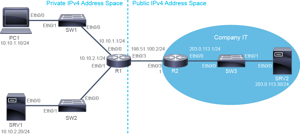
Job Aid
工作輔助資料
Device Information
裝置資訊
Device Information Table
裝置資訊表
Device 裝置 | Characteristic 特性 | Value 值 |
PC1 PC1 | IPv4 address IPv4 位址 | 10.10.1.10/24 10.10.1.10/24 |
PC1 PC1 | Default gateway 預設閘道 | 10.10.1.1 10.10.1.1 |
SRV1 SRV1 | IPv4 address IPv4 位址 | 10.10.2.20/24 10.10.2.20/24 |
SRV1 SRV1 | Default gateway 預設閘道 | 10.10.2.1 10.10.2.1 |
SRV1 SRV1 | Credentials 登入憑證 | admin / Cisco123 admin / Cisco123 |
SRV2 SRV2 | IPv4 address IPv4 位址 | 203.0.113.30/24 203.0.113.30/24 |
SRV2 SRV2 | Default gateway 預設閘道 | 203.0.113.1 203.0.113.1 |
SW1 SW1 | VLAN 1 IPv4 address VLAN 1 IPv4 位址 | 10.10.1.4/24 10.10.1.4/24 |
SW1 SW1 | Default gateway 預設閘道 | 10.10.1.1 10.10.1.1 |
SW1 SW1 | Ethernet0/0 description Ethernet0/0 描述 | Link to R1 連接至 R1 |
SW1 SW1 | Ethernet0/1 description Ethernet0/1 描述 | Link to PC1 連接至 PC1 |
SW2 SW2 | VLAN 1 IPv4 address VLAN 1 IPv4 位址 | 10.10.2.4/24 10.10.2.4/24 |
SW2 SW2 | Default gateway 預設閘道 | 10.10.2.1 10.10.2.1 |
SW2 SW2 | Ethernet0/0 description Ethernet0/0 描述 | Link to R1 連接至 R1 |
SW2 SW2 | Ethernet0/1 description Ethernet0/1 描述 | Link to SRV1 連接至 SRV1 |
SW3 SW3 | VLAN 1 IPv4 address VLAN 1 IPv4 位址 | 203.0.113.4/24 203.0.113.4/24 |
SW3 SW3 | Default gateway 預設閘道 | 203.0.113.1 203.0.113.1 |
SW3 SW3 | Ethernet0/0 description Ethernet0/0 描述 | Link to R2 連接至 R2 |
SW3 SW3 | Ethernet0/1 description Ethernet0/1 描述 | Link to SRV2 連接至 SRV2 |
R1 R1 | Ethernet0/0 description Ethernet0/0 描述 | Link to SW1 連接至 SW1 |
R1 R1 | Ethernet0/0 IPv4 address Ethernet0/0 IPv4 位址 | 10.10.1.1/24 10.10.1.1/24 |
R1 R1 | Ethernet0/1 description Ethernet0/1 描述 | Link to SW2 連接至 SW2 |
R1 R1 | Ethernet0/1 IPv4 address Ethernet0/1 IPv4 位址 | 10.10.2.1/24 10.10.2.1/24 |
R1 R1 | Ethernet0/3 description Ethernet0/3 描述 | Link to R2 連接至 R2 |
R1 R1 | Ethernet0/3 IPv4 address Ethernet0/3 IPv4 位址 | 198.51.100.2/24 198.51.100.2/24 |
R2 R2 | Ethernet0/0 description Ethernet0/0 描述 | Link to SW3 連接至 SW3 |
R2 R2 | Ethernet0/0 IPv4 address Ethernet0/0 IPv4 位址 | 203.0.113.1/24 203.0.113.1/24 |
R2 R2 | Ethernet0/3 description Ethernet0/3 描述 | Link to R1 連接至 R1 |
R2 R2 | Ethernet0/3 IPv4 address Ethernet0/3 IPv4 位址 | 198.51.100.1/24 198.51.100.1/24 |
Global IPv4 Address Networks
全域 IPv4 位址網路
Address Block 位址區塊 | Host Starting Address 起始主機位址 | Host Ending Address 結束主機位址 | Broadcast Address 廣播位址 | Subnet Mask 子網路遮罩 |
192.0.2.0/24 192.0.2.0/24 | 192.0.2.1 192.0.2.1 | 192.0.2.254 192.0.2.254 | 192.0.2.255 192.0.2.255 | 255.255.255.0 255.255.255.0 |
198.51.100.0/24 198.51.100.0/24 | 198.51.100.1 198.51.100.1 | 198.51.100.254 198.51.100.254 | 198.51.100.255 198.51.100.255 | 255.255.255.0 255.255.255.0 |
203.0.113.0/24 203.0.113.0/24 | 203.0.113.1 203.0.113.1 | 203.0.113.254 203.0.113.254 | 203.0.113.255 203.0.113.255 | 255.255.255.0 255.255.255.0 |
Task 1: Configure Static NAT
任務 1:設定靜態 NAT
Activity
活動
The R1 border router has been assigned a public IPv4 address by the ISP. On R1, set the IPv4 address of Ethernet0/3 to 198.51.100.2/24.
R1 邊界路由器已由 ISP 指派一個公開 IPv4 位址。請在 R1 上,將 Ethernet0/3 的 IPv4 位址設為 198.51.100.2/24。
On R1, enter the following commands:
在 R1 上,輸入以下指令:
R1# configure terminal
R1(config)# interface Ethernet0/3
R1(config-if)# ip address 198.51.100.2 255.255.255.0
R1(config-if)# exit
R1(config)#While still in the Global Configuration mode, use the do command to execute the Privileged Exec mode show ip interface brief command and verify the configuration of Ethernet0/3.
仍在全域設定模式下,使用 do 指令執行特權執行模式的 show ip interface brief 指令,驗證 Ethernet0/3 的設定。
On R1, enter the following command:
在 R1 上,輸入以下指令:
R1(config)# do show ip interface brief
Interface                  IP-Address      OK? Method Status                Protocol
Ethernet0/0                10.10.1.1       YES NVRAM  up                    up
Ethernet0/1                10.10.2.1       YES NVRAM  up                    up
Ethernet0/2                unassigned      YES NVRAM  administratively down down
Ethernet0/3 198.51.100.2    YES manual up                    up
Serial1/0                  unassigned      YES NVRAM  administratively down down
Serial1/1                  unassigned      YES NVRAM  administratively down down
Serial1/2                  unassigned      YES NVRAM  administratively down down
Serial1/3 unassigned YES NVRAM administratively down downStatically configure the IPv4 default route on R1, using the R2 interface as its next-hop IPv4 address.
在 R1 上以靜態方式設定 IPv4 預設路由,使用 R2 的介面作為下一跳 IPv4 位址。
On R1, enter the following command:
在 R1 上,輸入以下指令:
R1(config)# ip route 0.0.0.0 0.0.0.0 198.51.100.1Remain in the configuration mode and verify that the default route is now in the routing table.
留在設定模式中,驗證預設路由現在是否已出現在路由表中。
On R1, enter the following command:
在 R1 上,輸入以下指令:
R1(config)# do show ip route
Codes: L - local, C - connected, S - static, R - RIP, M - mobile, B - BGP
       D - EIGRP, EX - EIGRP external, O - OSPF, IA - OSPF inter area
       N1 - OSPF NSSA external type 1, N2 - OSPF NSSA external type 2
       E1 - OSPF external type 1, E2 - OSPF external type 2
       i - IS-IS, su - IS-IS summary, L1 - IS-IS level-1, L2 - IS-IS level-2
       ia - IS-IS inter area, * - candidate default, U - per-user static route
       o - ODR, P - periodic downloaded static route, H - NHRP, l - LISP
       + - replicated route, % - next hop override

Gateway of last resort is 198.51.100.1 to network 0.0.0.0

S*    0.0.0.0/0 [1/0] via 198.51.100.1
      10.0.0.0/8 is variably subnetted, 4 subnets, 2 masks
C        10.10.1.0/24 is directly connected, Ethernet0/0
L        10.10.1.1/32 is directly connected, Ethernet0/0
C        10.10.2.0/24 is directly connected, Ethernet0/1
L        10.10.2.1/32 is directly connected, Ethernet0/1
      198.51.100.0/24 is variably subnetted, 2 subnets, 2 masks
C        198.51.100.0/24 is directly connected, Ethernet0/3
L 198.51.100.2/32 is directly connected, Ethernet0/3While R1 does have access to the public IPv4 address space, systems within the private IPv4 address space of the topology do not verify this fact. Access the console of SRV1 and attempt to ping SRV2. This process should fail.
雖然 R1 確實能存取公開 IPv4 位址空間,但拓樸中位於私有 IPv4 位址空間內的系統並無法驗證這一點。請進入 SRV1 的主控台,嘗試 ping SRV2,此動作應該會失敗。
On SRV1, enter the following command to test access to the public IPv4 address space:
在 SRV1 上,輸入以下指令來測試對公開 IPv4 位址空間的存取:
SRV1(config)# do ping 203.0.113.30
Type escape sequence to abort.
Sending 5, 100-byte ICMP Echos to 203.0.113.30, timeout is 2 seconds:
.....
Success rate is 0 percent (0/5)
For the ping command to succeed, bidirectional connectivity must exist. In this case, the problem is not getting the ECHO requests from SRV1 to SRV2. Instead, the problem is a failure in getting the ECHO replies from SRV2 back to SRV1. Because NAT has not been configured, SRV2 is receiving IPv4 packets from the private IPv4 address of SRV1 (10.10.2.20). Routers on the internet are not aware of the private IPv4 address space within the networks that connect to the internet. When SRV2 generates an ECHO reply to 10.10.2.20 and sends that reply to R2 for forwarding, R2 does not have a route to use to forward the reply, so the reply is dropped.
ping 指令要成功,必須存在雙向連線。在此情況下,問題並非出在 ECHO 請求無法從 SRV1 送到 SRV2;問題在於 ECHO 回應無法從 SRV2 送回 SRV1。由於尚未設定 NAT,SRV2 收到的是來自 SRV1 私有 IPv4 位址(10.10.2.20)的 IPv4 封包。網際網路上的路由器並不知道連接到網際網路的網路內部使用的私有 IPv4 位址空間。當 SRV2 產生一個發往 10.10.2.20 的 ECHO 回應,並將該回應送給 R2 進行轉送時,R2 沒有可用來轉送此回應的路由,因此該回應會被丟棄。
SRV1 should be able to connect to the internet. Also, SRV1 should be accessible from the internet. Therefore, you will configure R1 to perform static inside IPv4 NAT for the SRV1 server. First, configure R1 interfaces for NAT. Ethernet0/1 is part of the inside network, and Ethernet0/3 is part of the outside networks. Return to the Global Configuration mode.
SRV1 應該要能連上網際網路,同時 SRV1 也應該能從網際網路被存取。因此,您將設定 R1 為 SRV1 伺服器執行靜態內部 IPv4 NAT。首先,為 NAT 設定 R1 的介面:Ethernet0/1 屬於內部網路,Ethernet0/3 屬於外部網路。請回到全域設定模式。
On R1, enter the following commands:
在 R1 上,輸入以下指令:
R1(config)# interface Ethernet0/1
R1(config-if)# ip nat inside
R1(config-if)# interface Ethernet0/3
R1(config-if)# ip nat outside
R1(config-if)# exitR1(config)#Add a static NAT configuration entry that translates the SRV1 IPv4 address (10.10.2.20) to public IPv4 address 198.51.100.2, and then leave the configuration mode.
新增一筆靜態 NAT 設定項目,將 SRV1 的 IPv4 位址(10.10.2.20)轉換為公開 IPv4 位址 198.51.100.2,然後離開設定模式。
On R1, enter the following command:
在 R1 上,輸入以下指令:
R1(config)# ip nat inside source static 10.10.2.20 198.51.100.2
R1(config)# end
R1#Display the translation table on R1.
顯示 R1 上的轉換表。
On R1, enter the following command:
在 R1 上,輸入以下指令:
R1# show ip nat translations
Pro Inside global      Inside local Outside local      Outside global
--- 198.51.100.2 10.10.2.20 --- ---
Static translations do not time out and remain in the translation table, regardless of whether they are used, for example, regardless of whether there is traffic to be translated. A static entry is persistent and will be present in the NAT translations table until it is manually removed.
靜態轉換不會逾時,無論是否有流量需要轉換,都會持續存在於轉換表中。靜態項目具有持久性,會一直存在於 NAT 轉換表中,直到手動移除為止。
The entry that you see in the NAT translations table is called a simple entry. It is a persistent entry that is associated with the configured static translation. As you can see, only inside mapping addresses are shown, because you only configured inside IPv4 static NAT. Outside addresses are empty. In the continuation of this activity, this translation will be used for specific traffic.
您在 NAT 轉換表中看到的項目稱為簡單項目(simple entry),是與所設定靜態轉換相關聯的持久性項目。如您所見,此處只顯示內部對應位址,因為您只設定了內部 IPv4 靜態 NAT,外部位址則為空白。在本活動的後續部分,此轉換將用於特定流量。
Access the console of SRV1 and test connectivity to SRV2 using ping.
進入 SRV1 的主控台,使用 ping 測試與 SRV2 的連線。
On SRV1, enter the following command:
在 SRV1 上,輸入以下指令:
SRV1# ping 203.0.113.30
Type escape sequence to abort.
Sending 5, 100-byte ICMP Echos to 203.0.113.30, timeout is 2 seconds:
!!!!!
Success rate is 100 percent (5/5), round-trip min/avg/max = 1/1/1 msReturn to the console of R1 and display the translation table.
回到 R1 的主控台,顯示轉換表。
On R1, enter the following command:
在 R1 上,輸入以下指令:
R1# show ip nat translations
Pro Inside global      Inside local       Outside local      Outside global
icmp 198.51.100.2:1   10.10.2.20:1       203.0.113.30:1     203.0.113.30:1
--- 198.51.100.2      10.10.2.20         ---                ---
The NAT translation table now shows two entries. The first entry is an extended entry because it includes more details than a simple entry. The extended entry also includes the protocol indication, the port numbers or protocol identifiers, and outside addresses. The extended entry is created when NAT is performed to translate specific traffic.
NAT 轉換表現在顯示兩筆項目。第一筆是延伸項目(extended entry),因為它包含比簡單項目更多的細節。延伸項目還包含通訊協定指示、連接埠號或協定識別碼,以及外部位址。延伸項目是在執行 NAT 以轉換特定流量時建立的。
Note that ICMP messages are encapsulated into packets, so the numbers shown after the IPv4 address and the colon are not port numbers. Instead, the translation information includes ICMP-specific message identifiers. In the example, the ICMP identifier has the value 1.
請注意,ICMP 訊息是封裝在封包中的,因此 IPv4 位址與冒號後面顯示的數字並不是連接埠號,而是 ICMP 專用的訊息識別碼。在此範例中,ICMP 識別碼的值為 1。
The second entry is a simple entry, which is a persistent entry associated with the configured static translation.
第二筆項目是簡單項目,是與所設定靜態轉換相關聯的持久性項目。
The most common use for static inside NAT translations is to provide a persistent IPv4 address that the systems in the public IPv4 address space can use to communicate with specific systems in the private IPv4 address space. Demonstrate this use. Access the console of SRV2 and establish a Telnet connection to SRV1. Make sure to use global SRV1 address. Use admin as username and Cisco123 as password.
靜態內部 NAT 轉換最常見的用途,是為公開 IPv4 位址空間中的系統提供一個持久性的 IPv4 位址,以便與私有 IPv4 位址空間中的特定系統通訊。請示範此用法:進入 SRV2 的主控台,建立一個到 SRV1 的 Telnet 連線,請務必使用 SRV1 的全域位址。使用者名稱請用 admin,密碼請用 Cisco123。
On SRV2, enter the following command:
在 SRV2 上,輸入以下指令:
SRV2# telnet 198.51.100.2
Trying 198.51.100.2 ... Open


User Access Verification

Username: admin
Password: Cisco123
SRV1>With the Telnet connection running, return to the console of R1 and view the translation table.
在 Telnet 連線仍在執行時,回到 R1 的主控台,檢視轉換表。
On R1, enter the following command:
在 R1 上,輸入以下指令:
R1# show ip nat translations
tcp 198.51.100.2:23   10.10.2.20:23      203.0.113.30:52975 203.0.113.30:52975
--- 198.51.100.2      10.10.2.20         ---                ---
There is the one simple entry that is associated with the configured static translation, and one extended entry, associated with the active Telnet session. The extended entry for the ICMP session has already timed out. In the extended entry, note the protocol indication tcp at the beginning of the entry and port number 23 alongside inside addresses.
此時有一筆與所設定靜態轉換相關聯的簡單項目,以及一筆與作用中 Telnet 工作階段相關聯的延伸項目。ICMP 工作階段的延伸項目已經逾時。在延伸項目中,請注意項目開頭的通訊協定指示 tcp,以及內部位址旁的連接埠號 23。
Access the console of SRV2 and close the Telnet session to SRV1.
進入 SRV2 的主控台,關閉與 SRV1 的 Telnet 工作階段。
On SRV2, enter the following command:
在 SRV2 上,輸入以下指令:
SRV1> exit

[Connection to 198.51.100.2 closed by foreign host]
SRV2#