As a Cisco proprietary technology, EtherChannel was initially implemented using the Cisco proprietary Port Aggregation Protocol (PAgP). Since the link aggregation concept has become widely adopted within the industry, to avoid interoperability issues, the aggregation control protocol was first standardized in the form of the IEEE 802.3ad standard or Link Aggregation Control Protocol (LACP). LACP is currently defined in IEEE 802.1AX. Because LACP is an IEEE standard, you can use it to facilitate EtherChannel in multivendor environments.
作為 Cisco 專屬技術,EtherChannel 最初是透過 Cisco 專屬的連接埠聚合協定(Port Aggregation Protocol,PAgP)實作的。隨著鏈路聚合概念在業界廣泛採用,為了避免互通性問題,聚合控制協定首先以 IEEE 802.3ad 標準,也就是鏈路聚合控制協定(Link Aggregation Control Protocol,LACP)的形式標準化。LACP 目前定義於 IEEE 802.1AX 之中。由於 LACP 是 IEEE 標準,你可以用它在多廠牌環境中促成 EtherChannel。
To implement aggregated logical links, you can choose to configure them statically or to configure a dynamic aggregation protocol to automatically create them. Static configuration is simpler, but more error prone. Link aggregation protocols define a dynamic negotiation procedure between adjoining switches. Using dynamic protocols provides a more efficient use of the aggregated logical link.
要實作聚合邏輯連結,你可以選擇以靜態方式設定,或設定動態聚合協定來自動建立。靜態設定較為簡單,但也較容易出錯。鏈路聚合協定定義了相鄰交換器之間的動態協商程序。使用動態協定能更有效率地運用聚合邏輯連結。
With LACP, you can control link aggregation (for example the maximum number of bundled ports allowed). LACP is also superior to static port channels with its automatic failover where traffic from a failed link within EtherChannel is sent over remaining working links in the EtherChannel.
透過 LACP,你可以控制鏈路聚合(例如允許的最大整合連接埠數量)。LACP 也優於靜態 port channel,因為它具備自動容錯移轉功能:當 EtherChannel 中某條連結故障時,其流量會透過 EtherChannel 中其餘正常運作的連結傳送。
LACP controls the bundling of physical interfaces to form a single logical interface. When you configure LACP, LACP packets are sent between LACP enabled ports to negotiate the forming of a channel. When LACP identifies matched Ethernet links, it groups the matching links into a logical EtherChannel link.
LACP 控制實體介面的整合,以形成單一邏輯介面。當你設定 LACP 時,啟用 LACP 的連接埠之間會傳送 LACP 封包,以協商建立通道。當 LACP 識別出相符的乙太網路連結時,會將這些相符的連結群組成一個邏輯 EtherChannel 連結。
The individual links must match on several parameters:
個別連結必須在下列幾項參數上相符:
- Interface types cannot be mixed, for instance FastEthernet or Gigabit Ethernet cannot be bundled into a single EtherChannel.介面類型不能混用,例如 FastEthernet 或 Gigabit Ethernet 不能整合成同一個 EtherChannel。
- Speed and duplexsettings must be the same on all the participating links.速度與雙工設定在所有參與的連結上必須相同。
- Switchport mode and VLAN information must match. Access ports must be assigned to the same VLAN. Trunk ports must have the same allowed range of VLANs. The native VLAN must be the same on all the participating links.Switchport 模式與 VLAN資訊必須相符。存取埠必須指派到相同的 VLAN。中繼埠必須允許相同範圍的 VLAN。原生 VLAN 在所有參與的連結上必須相同。
The best practice is to ensure that interfaces have consistent settings, before you enable LACP protocol on them. It is important to remember that interfaces on both sides must be consistently configured.
最佳做法是在介面上啟用 LACP 協定之前,先確保這些介面的設定一致。請務必記得,兩端的介面都必須以一致的方式設定。
The LACP protocol defines two modes:
LACP 協定定義了兩種模式:
- LACP active: This LACP mode places a port in an active negotiating state. In this state, the port initiates negotiations with other ports by sending LACP packets.LACP active:此 LACP 模式會將連接埠置於主動協商狀態。在此狀態下,該連接埠會傳送 LACP 封包,主動與其他連接埠展開協商。
- LACP passive: This LACP mode places a port in a passive negotiating state. In this state, the port responds to the LACP packets that it receives but it does not initiate LACP packet negotiation. The passive mode is useful when you do not know whether the remote system supports LACP.LACP passive:此 LACP 模式會將連接埠置於被動協商狀態。在此狀態下,該連接埠會回應收到的 LACP 封包,但不會主動展開 LACP 封包協商。當你不確定遠端系統是否支援 LACP 時,被動模式會很有用。
Manual static configuration places the interface in an EtherChannel manually, without any negotiation. No negotiation between the two switches means that there is no checking to make sure that all the ports have consistent settings. There are no link management mechanisms either.
手動靜態設定會在不經任何協商的情況下,手動將介面納入 EtherChannel。兩台交換器之間沒有協商,代表也不會檢查所有連接埠的設定是否一致,也沒有任何連結管理機制。
With static configuration, you define a mode for a port. There is only one static mode, the on mode. When static on mode is configured, the interface does not negotiate—it does not exchange any control packets. It immediately becomes part of the aggregated logical link, even if the port on the other side is disabled. With the on mode, the EtherChannel configuration is unconditional. If the port is not configured with the static on mode, then it is not meant to be included in the aggregated link.
使用靜態設定時,你會為連接埠定義一個模式。靜態模式只有一種,也就是on模式。設定為靜態 on 模式時,該介面不會進行協商,也就是不會交換任何控制封包。它會立即成為聚合邏輯連結的一部分,即使對端的連接埠已停用也一樣。在 on 模式下,EtherChannel 設定是無條件生效的。如果連接埠未設定為靜態 on 模式,就表示它並不打算被納入該聚合連結。
For the EtherChannel link to form, modes on both sides of the individual links must be compatible. The table shows which modes result in aggregation and which do not.
若要形成 EtherChannel 連結,個別連結兩端的模式必須相容。下表顯示哪些模式組合會產生聚合,哪些不會。
Channel Mode 通道模式 | Passive Passive | Active Active | On On |
Passive Passive | " " | OK OK | " " |
Active Active | OK OK | OK OK | " " |
On On | " " | " " | OK OK |
As you can see from the table, if you configure one side to be in passive mode, it will behave passively, waiting for the other side to initiate the EtherChannel negotiation. If the other side is also set to passive, the negotiation never starts and the EtherChannel does not form. If you disable all modes by using the no version of the command or if no mode is configured, then the interface is placed in the off mode and EtherChannel is disabled.
從表中可以看出,如果你將其中一端設定為passive模式,它會表現得很被動,等待另一端發起 EtherChannel 協商。如果另一端也設定為 passive,協商就永遠不會開始,EtherChannel 也就無法形成。如果你使用 no 版本的指令停用所有模式,或是沒有設定任何模式,該介面就會被置於 off 模式,EtherChannel 也會被停用。
For the LACP enabled link to be included in the EtherChannel, at least one of the ports must be configured with the active mode.
若要讓啟用 LACP 的連結被納入 EtherChannel,至少必須有一個連接埠設定為active模式。
The on mode manually places the interface in an EtherChannel, without any negotiation. It works only if the other side is also set to on. If the other side is set to negotiate parameters through LACP, no EtherChannel will form, because the side that is set to on mode will not negotiate.
on模式會在不經任何協商的情況下,手動將介面置入 EtherChannel。這種模式只有在對端也設定為 on 時才有效。如果對端設定為透過 LACP 協商參數,EtherChannel 就無法形成,因為設定為 on 模式的一端不會進行協商。
Note that once an EtherChannel is formed, whether by static configuration or dynamic negotiation, if a link within the EtherChannel fails, the EtherChannel will still be functional, as long as at least one physical link is active. The overall throughput would of course decrease in this situation.
請注意,無論是透過靜態設定還是動態協商形成的 EtherChannel,一旦形成之後,只要 EtherChannel 中至少有一條實體連結保持啟用,該 EtherChannel 就仍會正常運作,即使其中一條連結故障也一樣。在這種情況下,整體吞吐量當然會下降。

An advantage of configuring dynamic protocols to establish EtherChannel is protection from misconfigurations. LACP can ensure that the configuration at both ends fulfill the link aggregation requirements, before establishing an EtherChannel link. If you accidentally misconfigure a port or if you accidentally make a mistake in cabling, for instance, by plugging a cable in a trunk port on one side, and in an access port on the other side, LACP will not allow an EtherChannel link to form. With static link aggregation, a cabling or configuration mistake could go undetected and cause undesirable network behavior.
設定動態協定來建立 EtherChannel 的一項優點,是可以防範設定錯誤。LACP 能在建立 EtherChannel 連結之前,確保兩端的設定都符合鏈路聚合的要求。如果你不小心設定錯誤,或是在佈線時不小心出錯,例如把一端的線接到中繼埠,另一端卻接到存取埠,LACP 就不會讓 EtherChannel 連結形成。若採用靜態鏈路聚合,佈線或設定錯誤則可能未被偵測到,進而導致網路出現不良行為。
Because EtherChannel uses several links to transport packets through the physical infrastructure, the packets will be distributed between the physical links through load balancing. Load balancing takes place between links that are part of the same EtherChannel. Depending on the hardware platform, one or more load-balancing methods can be implemented. These methods include source MAC address to destination MAC address load balancing—or source IP address to destination IP address load balancing—across the physical links. Some methods can include source and destination port numbers as well.
由於 EtherChannel 使用多條連結透過實體基礎架構傳輸封包,這些封包會透過負載平衡分配到各條實體連結上。負載平衡發生在屬於同一個 EtherChannel 的連結之間。依硬體平台而定,可以實作一種或多種負載平衡方法,包括依來源 MAC 位址到目的 MAC 位址,或依來源 IP 位址到目的 IP 位址,在實體連結之間進行負載平衡。有些方法也可能將來源與目的連接埠號納入考量。
The goal of load balancing is not only to use all available links, but also to ensure that packets with the same header information will be forwarded on the same physical link to prevent unordered packet delivery. Load-balancing is performed in the hardware and is enabled by default.
負載平衡的目標不只是要使用所有可用的連結,還要確保帶有相同標頭資訊的封包會透過同一條實體連結轉送,以避免封包送達順序錯亂。負載平衡是在硬體中執行的,且預設為啟用。
After you configure an EtherChannel, any configuration changes applied to the port channel interface apply to all the physical ports assigned to the port channel interface. Configuration changes applied to the physical port affect only the port where you apply the configuration, so it is best not to change the configuration of a physical port once it is part of an EtherChannel. To change the parameters of all ports in an EtherChannel, apply configuration commands to the port channel interface—for example, spanning-tree commands or commands to configure a Layer 2 EtherChannel as a trunk.
設定好 EtherChannel 之後,任何套用在 port channel 介面上的設定變更,都會套用到指派給該 port channel 介面的所有實體連接埠。套用在實體連接埠上的設定變更,只會影響你套用設定的那個連接埠,因此,一旦連接埠成為 EtherChannel 的一部分,最好不要再變更該實體連接埠的設定。若要變更 EtherChannel 中所有連接埠的參數,應將設定指令套用到 port channel 介面,例如生成樹相關指令,或是將第 2 層 EtherChannel 設定為中繼埠的指令。
Layer 2 and Layer 3 EtherChannel
第 2 層與第 3 層 EtherChannel
Interfaces can be bundled into two types of EtherChannels, depending on the type of interfaces you are attempting to join to the port channel:
依你嘗試加入 port channel 的介面類型而定,介面可以整合成兩種類型的 EtherChannel:
- Layer 2 EtherChannel bundles access or trunk ports between switches or other devices (for example, servers).第 2 層 EtherChannel 會整合交換器之間或其他裝置(例如伺服器)之間的存取埠或中繼埠。
- Layer 3 EtherChannel bundles routed ports between switches or routers.第 3 層 EtherChannel 會整合交換器之間或路由器之間的路由連接埠。
Both Layer 2 and Layer 3 EtherChannels are common in an enterprise network. Layer 3 EtherChannel links are implemented within the LAN, mostly between Layer 3 switches, or between a Layer 3 switch and a router. Enterprises also implement Layer 3 EtherChannel on the links connecting to the WAN service provider, where the aggregated link is established between the enterprise edge router and the service provider’s router.
第 2 層與第 3 層 EtherChannel 在企業網路中都很常見。第 3 層 EtherChannel 連結通常在 LAN 內部實作,多半是在第 3 層交換器之間,或是在第 3 層交換器與路由器之間。企業也會在連接到 WAN 服務供應商的連結上實作第 3 層 EtherChannel,此時聚合連結是建立在企業邊界路由器與服務供應商的路由器之間。
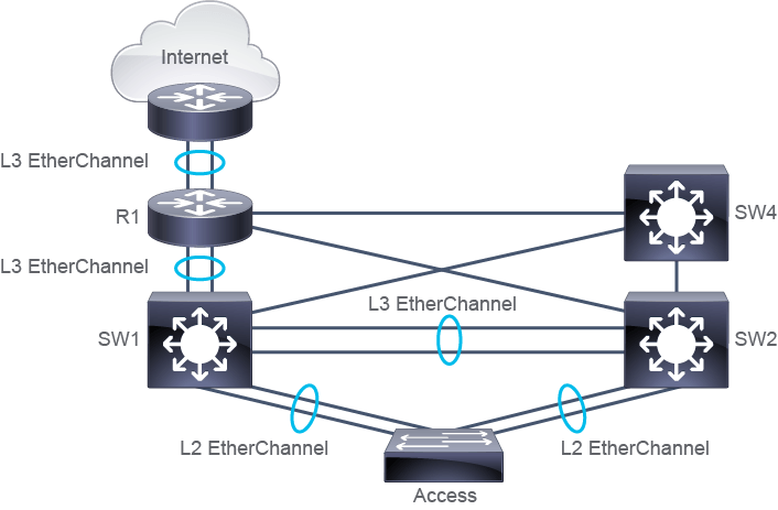
In the figure, you see an example of the enterprise LAN topology. Layer 2 and Layer 3 switches are connected using EtherChannel links, which consist of pairs of ports. Aggregated links that exist between SW1 and the Access switch and SW2 and the Access switch, are Layer 2 EtherChannel links. Aggregated links between the SW1 and SW2 switches and between the SW1 switch and router R1, are Layer 3 EtherChannel links.
圖中展示了一個企業 LAN 拓樸的範例。第 2 層與第 3 層交換器透過由多對連接埠組成的 EtherChannel 連結相互連接。SW1 與存取交換器之間,以及 SW2 與存取交換器之間的聚合連結,屬於第 2 層 EtherChannel 連結。SW1 與 SW2 交換器之間,以及 SW1 交換器與路由器 R1 之間的聚合連結,則屬於第 3 層 EtherChannel 連結。
When an aggregated link is a Layer 3 link, the IP addresses are assigned to the logical port channel interfaces on both sides of the link, and not to the member interfaces. A port channel for a Layer 3 aggregated link is a routed interface and it can have subinterfaces, just like other nonaggregated routed interfaces. It can also be enabled for routing protocols.
當聚合連結是第 3 層連結時,IP 位址會指派給連結兩端的邏輯 port channel 介面,而不是指派給成員介面。用於第 3 層聚合連結的 port channel 是一個路由介面,它可以像其他非聚合的路由介面一樣擁有子介面,也可以啟用路由協定。
The configuration options are the same for both types of EtherChannel links " you can choose to configure an aggregation protocol (LACP) or you can manually configure the link. Whatever the aggregation method you choose, ports you are aggregating must be of the same type, such as routed ports, and they must have the same attributes.
兩種類型的 EtherChannel 連結,設定選項是相同的,你可以選擇設定聚合協定(LACP),也可以手動設定該連結。無論你選擇哪種聚合方法,你所聚合的連接埠都必須是相同類型(例如都是路由連接埠),且必須具備相同的屬性。
WAN service providers sometimes implement Layer 1 devices in the connection from the customer’s router to the service provider router. Examples of these devices are media converters and multiplexers. This intermediary Layer 1 equipment might block LACP protocol messages. To ensure link aggregation, you should opt for static manual Layer 3 EtherChannel configuration.
WAN 服務供應商有時會在客戶路由器與服務供應商路由器之間的連線中,佈署第 1 層裝置,例如媒體轉換器與多工器。這類中介的第 1 層設備可能會阻擋 LACP 協定訊息。為確保鏈路聚合能夠成功,你應選擇採用靜態手動的第 3 層 EtherChannel 設定。
In the default Layer 3 switch configuration, the routing function is disabled and all ports are switched Layer 2 ports. Switched ports can be converted to routed ports. Routed ports behave like ports found on router platforms. Routed ports do not run Layer 2 management protocols, like STP, Dynamic Trunking Protocol (DTP), and others. Routed ports are not members of any VLANs manually configured on the switch. A routed port on a switch represents a boundary between different Layer 2 domains. Routed ports do not run STP, so ports don’t need to wait for STP calculations.
在預設的第 3 層交換器設定中,路由功能是停用的,所有連接埠都是交換式第 2 層連接埠。交換式連接埠可以轉換為路由連接埠。路由連接埠的行為就像路由器平台上的連接埠一樣。路由連接埠不會執行第 2 層管理協定,例如 STP、動態中繼協定(Dynamic Trunking Protocol,DTP)等。路由連接埠不屬於交換器上手動設定的任何 VLAN。交換器上的路由連接埠,代表了不同第 2 層網域之間的邊界。由於路由連接埠不執行 STP,因此這些連接埠不需要等待 STP 計算完成。
For successful establishment of a Layer 3 EtherChannel link, physical ports on each side of the aggregated link must be configured as routed ports. They also must have matching port attributes, such as bandwidth and duplex mode.
要成功建立第 3 層 EtherChannel 連結,聚合連結兩端的實體連接埠都必須設定為路由連接埠,同時也必須具備相符的連接埠屬性,例如頻寬與雙工模式。
In addition, the logical port channel interface must be a routed interface. A Layer 3 EtherChannel will become active only when both the aggregated interface and its constituent physical interfaces are routed interfaces.
此外,邏輯 port channel 介面也必須是路由介面。只有當聚合介面及其成員實體介面都是路由介面時,第 3 層 EtherChannel 才會啟用。
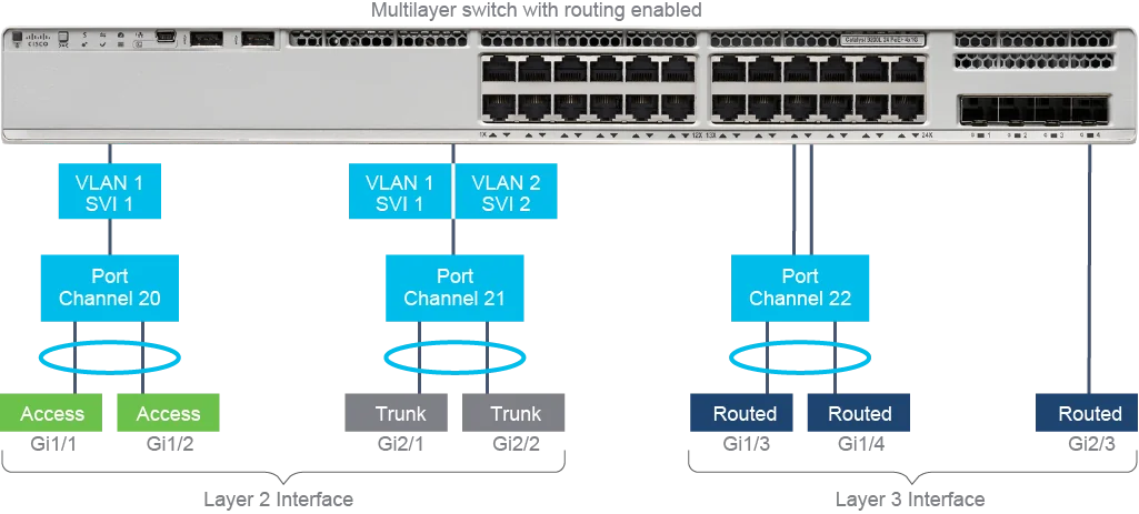
The figure shows a Layer 3 switch with routing enabled and illustrates the difference between Layer 2 and Layer 3 EtherChannel. In the figure, there are three aggregated links, represented by logical interfaces port-channel 20, port-channel 21, and port-channel 22. For simplicity, the figure does not include images of remote devices the EtherChannels would be connected to, such as another Layer 3 switch or a server.
此圖展示了一台啟用路由功能的第 3 層交換器,並說明第 2 層與第 3 層 EtherChannel 之間的差異。圖中有三條聚合連結,分別以邏輯介面 port-channel 20、port-channel 21 與 port-channel 22 表示。為求簡化,圖中並未畫出這些 EtherChannel 所連接的遠端裝置(例如另一台第 3 層交換器或伺服器)。
Port-channel 20 is an access Layer 2 logical interface for the aggregated link that bundles physical ports GigabitEthernet 1/1 and GigabitEthernet 1/2. Note that both GigabitEthernet 1/1 and GigabitEthernet 1/2 have the same Layer 2 attributes: they are both access ports and they both belong to VLAN 1.
Port-channel 20 是一個存取型第 2 層邏輯介面,用於整合實體連接埠 GigabitEthernet 1/1 與 GigabitEthernet 1/2 的聚合連結。請注意,GigabitEthernet 1/1 與 GigabitEthernet 1/2 具有相同的第 2 層屬性:兩者都是存取埠,且都屬於 VLAN 1。
Similarly, port-channel 21 is a trunk Layer 2 logical interface for the aggregated link that bundles GigabitEthernet 2/1 and GigabitEthernet 2/2 physical interfaces. Both GigabitEthernet 2/1 and GigabitEthernet 2/2 are configured as trunks and allow the same VLANs: VLAN 1 and VLAN 2.
同樣地,port-channel 21 是一個中繼型第 2 層邏輯介面,用於整合實體介面 GigabitEthernet 2/1 與 GigabitEthernet 2/2 的聚合連結。GigabitEthernet 2/1 與 GigabitEthernet 2/2 都設定為中繼埠,並允許相同的 VLAN:VLAN 1 與 VLAN 2。
VLAN 1 and VLAN 2 have corresponding Switch Virtual Interfaces (SVIs) configured. These SVIs provide Layer 3 IP connectivity to their corresponding VLANs. Although related to those SVIs, both EtherChannels that are represented by port-channel 20 and port-channel 21 are still Layer 2 aggregated links, for example, they run Layer 2 management protocols.
VLAN 1 與 VLAN 2 都設定了對應的交換器虛擬介面(Switch Virtual Interface,SVI)。這些 SVI 為對應的 VLAN 提供第 3 層 IP 連線能力。雖然與這些 SVI 相關,但由 port-channel 20 與 port-channel 21 所代表的兩個 EtherChannel 仍然是第 2 層聚合連結,例如它們仍會執行第 2 層管理協定。
Port-channel 22 is a routed logical interface for the aggregated link that bundles physical ports GigabitEthernet 1/3 and GigabitEthernet 1/4. Both GigabitEthernet 1/3 and GigabitEthernet 1/4 are configured as routed ports. The figure also shows an unaggregated routed port GigabitEthernet 2/3.
Port-channel 22 是一個路由邏輯介面,用於整合實體連接埠 GigabitEthernet 1/3 與 GigabitEthernet 1/4 的聚合連結。GigabitEthernet 1/3 與 GigabitEthernet 1/4 都設定為路由連接埠。圖中還顯示了一個未聚合的路由連接埠 GigabitEthernet 2/3。