EtherChannel bundles individual links into a single logical interface called a port channel. There are slight differences in the configuration of Layer 2 EtherChannel and Layer 3 EtherChannel. For both types of EtherChannels, you configure interface bundling on physical interfaces. Once interfaces are bundled, you configure aggregated link parameters on the logical port-channel interface.
EtherChannel 將多條實體鏈路捆綁成一個單一的邏輯介面,稱為連接埠通道(port channel)。第 2 層 EtherChannel 與第 3 層 EtherChannel 的設定方式略有不同。無論哪一種類型,都要先在實體介面上設定鏈路捆綁,捆綁完成後,再於邏輯連接埠通道介面上設定聚合鏈路的參數。
Configuring EtherChannel
設定 EtherChannel
Requirements and restrictions for EtherChannel configuration include:
設定 EtherChannel 的需求與限制包括:
- All Ethernet interfaces must support EtherChannel.所有乙太網路介面都必須支援 EtherChannel。
- The same configuration options must be supported on both devices connected with the aggregated link. You should verify which configuration options are available on devices. Some router platforms support only manual configuration.連接聚合鏈路的兩台裝置,必須支援相同的設定選項。您應該先確認裝置上有哪些設定選項可用。部分路由器平台僅支援手動設定。
- You can typically group from two to eight physical ports, but some platforms allow more ports to be included. Verify the maximum allowed number of ports that you can bundle.通常可以將二到八個實體連接埠分為一組,但部分平台允許包含更多連接埠。請確認平台允許捆綁的最大連接埠數量。
- The interface mode, switched or routed, should be the same for aggregated interface and for member interfaces.聚合介面與成員介面的介面模式(交換式或路由式)必須相同。
- You cannot mix port types within a single EtherChannel. For example, you could group four FastEthernet ports into one logical Ethernet link, but you could not group two FastEthernet ports and two GigabitEthernet ports into one logical Ethernet link. There is no requirement that the interfaces should be physically contiguous, or on the same module.同一個 EtherChannel 內不能混用不同類型的連接埠。例如,您可以將四個 FastEthernet 連接埠分組為一條邏輯乙太網路鏈路,但不能將兩個 FastEthernet 連接埠與兩個 GigabitEthernet 連接埠分為同一條邏輯乙太網路鏈路。介面不需要在實體上相鄰,也不需要位於同一模組上。
- All ports on both devices must be correctly configured. The individual links must match on several parameters:兩台裝置上的所有連接埠都必須正確設定。各條個別鏈路必須在下列幾個參數上一致:
- Speed and duplex settings must be the same on all the participating links.所有參與的鏈路上,速度與雙工設定必須相同。
- Interface mode must match: you cannot aggregate switched and routed ports in the same EtherChannel.介面模式必須相符:不能將交換式連接埠與路由式連接埠聚合在同一個 EtherChannel 中。
- Switchport mode must match: all interfaces in the EtherChannel bundle must be assigned to the same VLAN or be configured as a trunk.交換埠模式必須相符:EtherChannel 捆綁中的所有介面,必須指派給相同的 VLAN,或都設定為中繼埠。
- VLAN information must match: access ports must be assigned to the same VLAN. Trunk ports must have the same allowed range of VLANs. The native VLAN must be the same on all the participating links.VLAN 資訊必須相符:存取埠必須指派給相同的 VLAN。中繼埠必須允許相同範圍的 VLAN。所有參與的鏈路上,原生 VLAN 必須相同。
Ensure that interfaces have consistent settings before you bundle them. If you have to change these settings later, configure them on the corresponding port channel interface.
在捆綁介面之前,請先確保這些介面的設定一致。若之後需要變更這些設定,應在對應的連接埠通道介面上進行設定。
After you configure the port channel interface, any configuration that you apply to the port channel interface affects member interfaces as well. The opposite does not apply and will cause interface incompatibility and link suspension from the EtherChannel.
設定完連接埠通道介面後,您在該介面上套用的任何設定都會影響到所有成員介面。反之則不然,若在成員介面上單獨設定,會造成介面不相容,並導致該鏈路從 EtherChannel 中被暫停。
It is recommended that you configure LACP protocol to establish EtherChannel links, if the platform you are working on supports it. LACP can prevent misconfiguration issues by ensuring that configurations at both ends of the aggregated link fulfill the link aggregation requirements.
若所使用的平台支援 LACP 協定,建議使用 LACP 來建立 EtherChannel 鏈路。LACP 可以確保聚合鏈路兩端的設定都符合鏈路聚合的需求,藉此避免設定錯誤的問題。
To ensure configuration consistency of the physical interfaces, you can use the interface range command. The syntax of the command requires that you enter the interface type, followed by identifiers of the first and the last interface in the range.
為確保實體介面的設定一致,您可以使用 interface range 指令。此指令的語法要求您輸入介面類型,接著輸入範圍內第一個與最後一個介面的識別碼。
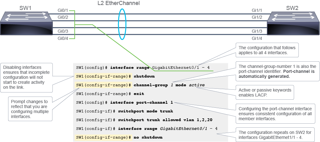
The example in the figure shows how the interface range command is used to configure four GigabitEthernet interfaces of SW1. The range is specified by providing interface type (GigabitEthernet), and identifiers of the first interface and the last interface (0/1–4). The command in the example specifies four interfaces, the first being GigabitEthernet 0/1, and the last being GigabitEthernet 0/4. Once you specify the range, all the configuration commands that follow apply to all the interfaces included in the range. Using the interface range command, you easily ensure that all the interfaces have the same configuration. A similar configuration must be applied on the SW2 switch also.
圖中的範例展示了如何使用 interface range 指令,設定 SW1 上的四個 GigabitEthernet 介面。此範圍是透過指定介面類型(GigabitEthernet),以及第一個介面與最後一個介面的識別碼(0/1–4)來指定。範例中的指令指定了四個介面,第一個是 GigabitEthernet 0/1,最後一個是 GigabitEthernet 0/4。指定範圍之後,後續輸入的所有設定指令都會套用到該範圍內的所有介面。使用 interface range 指令,您可以輕鬆確保所有介面設定一致。SW2 交換器上也必須套用類似的設定。
Once you successfully bundle the ports, you can ensure consistent configuration by applying it to the port channel interface.
成功捆綁連接埠之後,您可以透過在連接埠通道介面上套用設定,來確保設定的一致性。
When configuring EtherChannel, a good practice is to start by shutting down the interfaces to be aggregated, so that incomplete configuration will not start to create activity on the link.
設定 EtherChannel 時,好的做法是先將要聚合的介面關閉,這樣不完整的設定就不會在鏈路上產生活動。
After shutting down the member interfaces, proceed by using the channel-group command to specify the port channel identifier, also called channel group number, and the method for establishing the aggregated link.
關閉成員介面之後,接著使用 channel-group 指令,指定連接埠通道識別碼(也稱為通道群組編號),以及建立聚合鏈路的方法。
The command syntax is channel-group channel-group-number mode { on } | { active | passive }.
指令語法為 channel-group channel-group-number mode { on } | { active | passive }。
- The
channel-groupcommand assigns the interface to the port channel interface and automatically creates the port channel interface. The channel-group-number specifies the identifier of the port channel interface for the aggregated link.channel-group指令會將介面指派給連接埠通道介面,並自動建立該連接埠通道介面。channel-group-number 指定的是該聚合鏈路對應之連接埠通道介面的識別碼。 - With the
modekeyword, thechannel-groupcommand also specifies the method for link aggregation. The keywords specifying the link aggregation method have the following meanings:透過mode關鍵字,channel-group指令也會指定鏈路聚合的方法。這些指定鏈路聚合方法的關鍵字,其意義如下:on: Forces the port to aggregate without LACP. In theonmode, an EtherChannel is established only when a port group in the on mode is connected to another port group in the on mode.on:強制連接埠在不使用 LACP 的情況下進行聚合。在on模式下,只有當一組使用 on 模式的連接埠群組,連接到另一組同樣使用 on 模式的連接埠群組時,EtherChannel 才會建立。active: Enables LACP only if a LACP device is detected at the other end of the link. The active mode places the port into an active negotiating state in which the port starts negotiations with other port by sending LACP packets.active:只有在鏈路另一端偵測到支援 LACP 的裝置時,才會啟用 LACP。active 模式會將連接埠置於主動協商狀態,該連接埠會發送 LACP 封包,主動與其他連接埠展開協商。passive: Enables LACP on the port and places it into a passive negotiating state in which the port responds to LACP packets that it receives, but does not start LACP packet negotiationpassive:在連接埠上啟用 LACP,並將其置於被動協商狀態,該連接埠會回應收到的 LACP 封包,但不會主動發起 LACP 封包協商
The example configuration in the previous figure bundles GigabitEthernet0/1, GigabitEthernet0/2, GigabitEthernet0/3, and GigabitEthernet0/4 into a Layer 2 EtherChannel link represented by the logical interface port-channel 1. Layer 2 settings of the EtherChannel interface, trunking, and VLANs allowed on the trunk, are configured on the logical port channel interface.
先前圖中的範例設定,將 GigabitEthernet0/1、GigabitEthernet0/2、GigabitEthernet0/3 與 GigabitEthernet0/4 捆綁成一條由邏輯介面 port-channel 1 表示的第 2 層 EtherChannel 鏈路。EtherChannel 介面的第 2 層設定,包括中繼功能,以及中繼埠上允許的 VLAN,都是在邏輯連接埠通道介面上設定的。
The following list summarizes the steps used to configure Layer 2 EtherChannel:
以下清單彙整了設定第 2 層 EtherChannel 的步驟:
- Use
interface rangecommand to configure interface attributes for interfaces that are being aggregated [optional].使用interface range指令,為即將聚合的介面設定屬性〔選用〕。 - Shut down interfaces that will be aggregated, using the
shutdowncommand.使用shutdown指令,關閉即將聚合的介面。 - Bundle the interfaces using
channel-groupcommand by specifying the port channel identifier and aggregation method:使用channel-group指令,指定連接埠通道識別碼與聚合方法,藉此捆綁介面:- Choose
onfor manual unconditional aggregation選擇on進行手動、無條件的聚合 - Choose
activeorpassiveto enable LACP選擇active或passive以啟用 LACP
- Configure the port channel interface.設定連接埠通道介面。
- Enable interfaces that were previously shut down.啟用先前關閉的介面。
To configure Layer 2 EtherChannel, you do not need to change the default settings for the interface modes. On switches, physical interfaces and port channel interfaces are Layer 2 ports, or switched ports, by default.
設定第 2 層 EtherChannel 時,您不需要變更介面模式的預設設定。在交換器上,實體介面與連接埠通道介面預設都是第 2 層連接埠,也就是交換式連接埠。
When configuring Layer 3 EtherChannel on a Layer 3 switch, there are several specifics that you normally do not encounter with Layer 2 EtherChannels.
在第 3 層交換器上設定第 3 層 EtherChannel 時,會遇到幾項在第 2 層 EtherChannel 中通常不會碰到的特殊情況。
First, you should ensure that the interfaces that you are aggregating are all routed interfaces—and that applies to both the port channel interface and to member interfaces. When configuring Layer 3 EtherChannels, it is recommended that you first manually create the port channel logical interface, and convert it to the routed interface.
首先,您應確保要聚合的介面都是路由式介面,這適用於連接埠通道介面與成員介面兩者。設定第 3 層 EtherChannel 時,建議先手動建立連接埠通道邏輯介面,再將其轉換為路由式介面。
To create the port channel logical interface, use the interface port-channelport-channel-identifier global configuration mode command. By default, port channel interface is a Layer 2 interface. Therefore, use the no switchport command to make it a routed interface. The no switchport command deletes any configuration specific to Layer 2 on the interface.
若要建立連接埠通道邏輯介面,請使用全域設定模式指令 interface port-channelport-channel-identifier。連接埠通道介面預設為第 2 層介面,因此請使用 no switchport 指令,將其轉為路由式介面。no switchport 指令會刪除介面上所有第 2 層相關的設定。
In the next step, you configure the port channel interface with an IP version 4 (IPv4) address using the ip address command. Note that the IPv4 address is assigned to the logical port channel interface, and not to any of the member physical interfaces. If a member interface already has an IPv4 address assigned, and you wish to assign the same IPv4 address to the port channel interface, you must first delete the IPv4 address from the member interface before configuring it on the port channel interface.
下一步,使用 ip address 指令,為連接埠通道介面設定第 4 版網際網路通訊協定(IPv4)位址。請注意,這個 IPv4 位址是指派給邏輯連接埠通道介面,而不是任何成員實體介面。若某個成員介面已經指派了 IPv4 位址,而您想將相同的 IPv4 位址指派給連接埠通道介面,就必須先從該成員介面刪除該 IPv4 位址,再將其設定於連接埠通道介面上。
Finally, you should configure member interface bundling. For successful bundling to a Layer 3 EtherChannel, all member interfaces must be routed interfaces. Use the no switchport command to make the interfaces routed interfaces.
最後,您應設定成員介面的捆綁。要成功捆綁為第 3 層 EtherChannel,所有成員介面都必須是路由式介面。請使用 no switchport 指令,將這些介面轉為路由式介面。
The command used to bundle member interfaces is the same as for the Layer 2 EtherChannels. Use the channel-group command to specify the port channel identifier and the method of aggregation. The port channel identifier that you choose for the logical interface must match the number you use with the channel-group command when configuring member interfaces.
用來捆綁成員介面的指令,與第 2 層 EtherChannel 相同。使用 channel-group 指令,指定連接埠通道識別碼與聚合方法。您為邏輯介面選擇的連接埠通道識別碼,必須與設定成員介面時搭配 channel-group 指令所使用的編號相符。
Use LACP where the platforms allow it. If the platform does not support aggregation protocols, you have to configure static aggregation. Beware that, with static configuration, misconfigurations on devices are not going to be detected automatically.
只要平台允許,就應使用 LACP。若平台不支援聚合協定,就必須設定靜態聚合。請注意,使用靜態設定時,裝置上的設定錯誤不會被自動偵測到。
The following is an example of Layer 3 EtherChannel configuration.
以下是第 3 層 EtherChannel 設定的範例。
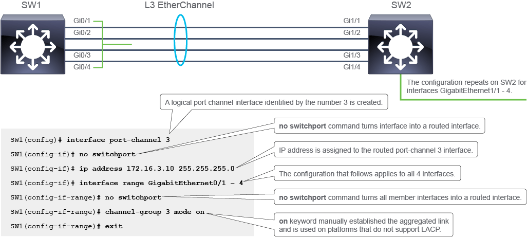
The example in the figure shows the configuration of a Layer 3 EtherChannel link between two Layer 3 switches. The configuration example is given only for the SW1 switch. A similar configuration must be applied on the SW2 switch also.
圖中的範例展示了兩台第 3 層交換器之間,第 3 層 EtherChannel 鏈路的設定。此設定範例僅針對 SW1 交換器提供。SW2 交換器上也必須套用類似的設定。
The first line of the configuration creates a logical port channel interface with the identifier 3. When the port channel interface does not exist, it is created using interface port-channel command. The port channel interface is configured as a routed interface using the no switchport command. Once the port channel interface is a routed interface, you can configure Layer 3 parameters, such as the IPv4 address. The IPv4 address assigned to the port-channel 3 interface on SW 1 is 172.16.3.10/24.
設定的第一行建立了一個識別碼為 3 的邏輯連接埠通道介面。當該連接埠通道介面尚不存在時,會使用 interface port-channel 指令建立。接著使用 no switchport 指令,將該連接埠通道介面設定為路由式介面。一旦連接埠通道介面成為路由式介面,就可以設定第 3 層參數,例如 IPv4 位址。SW1 上指派給 port-channel 3 介面的 IPv4 位址為 172.16.3.10/24。
To configure member interface bundling, the example uses the interface range command. All member interfaces are converted to routed interfaces using the no switchport command. Interface bundling is specified with the channel-group command. The channel-group identifier is 3, which matches the identifier of the previously created port channel interface. The aggregation method is set to on, which means that the interfaces are bundled manually. For the Layer 3 EtherChannel to be fully operational, the configuration on SW2 switch must specify the same aggregation method. The port channel identifier does not need to match between SW1 and SW2 switches, but it is best practice that they do match.
為設定成員介面的捆綁,此範例使用了 interface range 指令。所有成員介面都透過 no switchport 指令轉換為路由式介面。介面捆綁則以 channel-group 指令指定。channel-group 識別碼為 3,與先前建立的連接埠通道介面識別碼相符。聚合方法設為 on,代表這些介面是以手動方式捆綁。若要讓第 3 層 EtherChannel 完全正常運作,SW2 交換器上的設定必須指定相同的聚合方法。SW1 與 SW2 交換器的連接埠通道識別碼不需要相符,但讓兩者相符是最佳做法。
The following list summarizes the steps used to configure Layer 3 EtherChannel:
以下清單彙整了設定第 3 層 EtherChannel 的步驟:
- Create a logical port channel interface using the
interface port-channelcommand.使用interface port-channel指令,建立邏輯連接埠通道介面。 - Turn the logical port channel interface into routed interface, using the
no switchportcommand.使用no switchport指令,將該邏輯連接埠通道介面轉為路由式介面。 - Assign IPv4 address to the port channel interface.為連接埠通道介面指派 IPv4 位址。
- Use the
interface rangecommand to configure member interfaces:使用interface range指令設定成員介面:- Convert member interfaces into routed ports using the
no switchportcommand使用no switchport指令,將成員介面轉換為路由式連接埠 - Bundle the interfaces using the
channel-groupcommand by specifying the logical interface identifier and aggregation method: chooseonfor manual unconditional aggregation, or chooseactiveorpassiveto enable LACP.使用channel-group指令,指定邏輯介面識別碼與聚合方法,藉此捆綁介面:選擇on進行手動、無條件的聚合,或選擇active或passive以啟用 LACP。
Verifying EtherChannel Configuration
驗證 EtherChannel 設定
You can use several commands to verify an EtherChannel configuration. Using verification commands, you can make sure that EtherChannel link is operational, at which layer it is operating, whether all its member interfaces are active, which aggregation method is configured, and so on.
您可以使用多個指令來驗證 EtherChannel 設定。透過驗證指令,您可以確認 EtherChannel 鏈路是否正常運作、運作於哪一層、所有成員介面是否都已啟用、目前設定的是哪一種聚合方法等等。
The following commands are available for EtherChannel verification in Cisco IOS Software:
Cisco IOS 軟體中,可用於 EtherChannel 驗證的指令如下:
- The
show interface port-channelcommand displays the general status of the logical port channel interface that represents the aggregated link. In the example, the interface port-channel 1 is operational.show interface port-channel指令會顯示代表聚合鏈路之邏輯連接埠通道介面的一般狀態。在範例中,port-channel 1 介面正常運作。SW1# show interface Port-channel1 Port-channel1 is up, line protocol is up (connected) Hardware is EtherChannel, address is 000f.34f9.9182 (bia 000f.34f9.9182) MTU 1500 bytes, BW 200000 Kbit, DLY 100 usec, reliability 255/255, txload 1/255, rxload 1/255 Encapsulation ARPA, loopback not set <... output omitted ...> - The
show etherchannel summarycommand displays one line of information per port channel and is particularly useful when several port channel interfaces are configured on the same device. The output of the command provides, among other, information on port channel interface status, method used for link aggregation, member interfaces, and their status. In the example output, the switch has one EtherChannel configured; group 1 uses LACP. The interface bundle consists of the FastEthernet0/1 and FastEthernet0/2 interfaces; the letter P indicates that these ports are bundled. You can see that the aggregated link is a Layer 2 EtherChannel, and that it is in use. The letters SU indicate that the interface is a Layer 2 interface: The letter S stands for Layer 2 and the letter U stands for in use.show etherchannel summary指令會針對每個連接埠通道顯示一行資訊,當同一台裝置上設定了多個連接埠通道介面時,這個指令特別有用。此指令的輸出提供了連接埠通道介面狀態、鏈路聚合所使用的方法、成員介面及其狀態等資訊。在範例輸出中,該交換器設定了一個 EtherChannel;群組 1 使用 LACP。此介面捆綁由 FastEthernet0/1 與 FastEthernet0/2 介面組成;字母 P 表示這些連接埠已被捆綁。您可以看到,此聚合鏈路是第 2 層 EtherChannel,且目前正在使用中。字母 SU 表示該介面為第 2 層介面:字母 S 代表第 2 層,字母 U 代表使用中。SW2# show etherchannel summary Flags: D - down P - bundled in port-channel I - stand-alone s - suspended H - Hot-standby (LACP only) R - Layer3 S - Layer2 U - in use f - failed to allocate aggregator M - not in use, minimum links not met u - unsuitable for bundling w - waiting to be aggregated d - default port Number of channel-groups in use: 1 Number of aggregators: 1 Group Port-channel Protocol Ports ------+-------------+-----------+---------------------------------------- 1 Po1(SU) LACP Fa0/1(P) Fa0/2(P) - The
show etherchannel port-channelcommand displays information about the specific port channel interface. In the output, the Group:field indicates the port channel identifier, which is 1 in the example. The protocol used to bundle the ports is indicated in the Protocol: output field, and it is LACP in the example. Member interfaces are indicated in the table called Ports in the Port-channel: and, in this example, the members are two physical interfaces FastEthernet0/1 and FastEthernet0/2. The EC state indicates whether the member interface is operational, for instance, whether it actively participates in the EtherChannel. The example output shows that both member interfaces are active.show etherchannel port-channel指令會顯示特定連接埠通道介面的相關資訊。在輸出中,Group:欄位表示連接埠通道識別碼,在範例中為 1。用於捆綁連接埠的協定,會顯示在 Protocol: 輸出欄位中,範例中為 LACP。成員介面則顯示於名為 Ports in the Port-channel: 的表格中,在此範例中,成員為兩個實體介面 FastEthernet0/1 與 FastEthernet0/2。EC state 表示成員介面是否正常運作,例如,是否確實有主動參與 EtherChannel。範例輸出顯示,兩個成員介面都處於啟用狀態。Switch# show etherchannel Port-channel Channel-group listing: ---------------------- Group: 1 ---------- Port-channels in the group: --------------------------- Port-channel: Po1 (Primary Aggregator) ------------ Age of the Port-channel = 4d:01h:29m:00s <... output omitted ...> Protocol = LACP <... output omitted ...> Ports in the Port-channel: Index Load Port EC state No of bits ------+------+------+------------------+----------- 0 00 Fa0/1 Active 4 1 00 Fa0/2 Active 4 Time since last port bundled: 0d:00h:00m:18s Fa0/2 Time since last port Un-bundled: 0d:00h:00m:32s Fa0/2 - The
show etherchannel summarycommand displays a summary of EtherChannel information. In the following example, you see summarized information about the Layer 3 EtherChannel links on an SW1 switch.show etherchannel summary指令會顯示 EtherChannel 資訊的摘要。在以下範例中,您可以看到 SW1 交換器上第 3 層 EtherChannel 鏈路的摘要資訊。SW1# show etherchannel summary Flags: D - down P - bundled in port-channel I - stand-alone s - suspended H - Hot-standby (LACP only) R - Layer3 S - Layer2 U - in use f - failed to allocate aggregator M - not in use, minimum links not met u - unsuitable for bundling w - waiting to be aggregated d - default port Number of channel-groups in use: 1 Number of aggregators: 1 Group Port-channel Protocol Ports ------+-------------+-----------+----------------------------------------------- 1 Po5(RU) - Gi0/1(P) Gi0/2(P)The one-line summary shows the "RU" indication next to the Po5 interface label. The "R" tells you that port-channel 5 represents a Layer 3 EtherChannel. The member interfaces GigabitEthernet 0/1 and GigabitEthernet 0/2, are indeed bundled, because the "P" flag, standing for "bundled in port-channel" is next to each of them. Note that this command will not give you information about the IPv4 address configured, which you can obtain using the
show ip interface port-channel5 command此摘要中,Po5 介面標籤旁顯示了「RU」標記。「R」表示 port-channel 5 是一個第 3 層 EtherChannel。成員介面 GigabitEthernet 0/1 與 GigabitEthernet 0/2 確實已被捆綁,因為它們旁邊都標有代表「已捆綁至連接埠通道」的「P」旗標。請注意,此指令不會提供已設定 IPv4 位址的相關資訊,您可以使用
show ip interface port-channel5 指令來取得該資訊GigabitEthernet 0/1 and GigabitEthernet 0/2 will now behave as one virtual Layer 3 physical interface. For instance, if you issue the
show ip routecommand, routes will be seen as being accessible through PortChannel 5 and not either GigabitEthernet 0/1 or GigabitEthernet 0/2, as illustrated in the following example output:GigabitEthernet 0/1 與 GigabitEthernet 0/2 現在會表現得像一個虛擬的第 3 層實體介面。舉例來說,若您執行
show ip route指令,會看到路由是透過 PortChannel 5 存取,而不是透過 GigabitEthernet 0/1 或 GigabitEthernet 0/2,如以下範例輸出所示:SW1# show ip route < output omitted > 172.16.0.0/24 is subnetted, 2 subnets C 172.16.1.0 is directly connected, Loopback0 O 172.16.2.0 [110/2] via 192.168.1.2, 00:02:37, Port-channel5 C 192.168.1.0/24 is directly connected, Port-channel5