Introduction
簡介
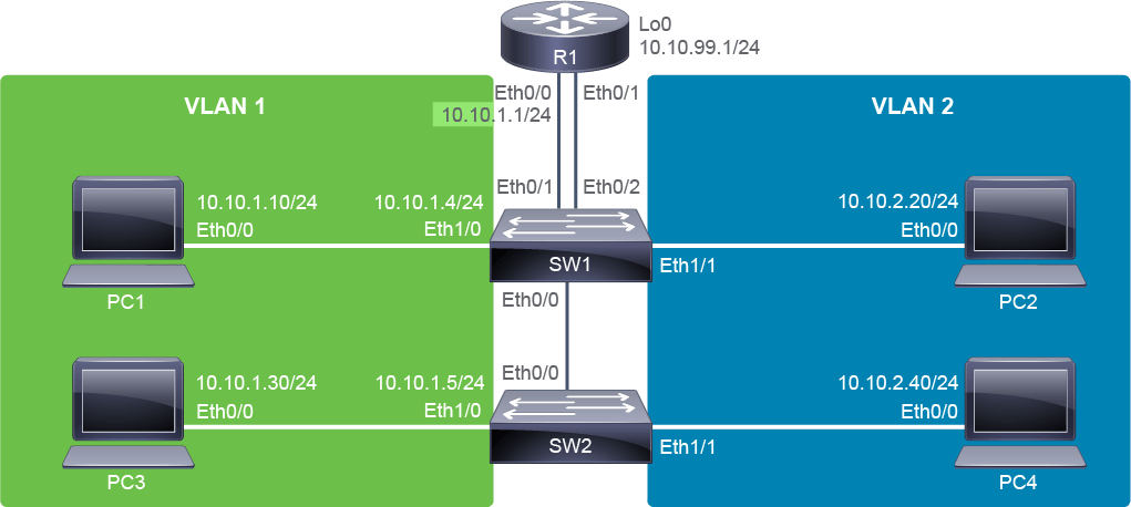
This lab exercise will guide you through routing between VLANs. The devices are configured as shown in the topology diagram. Currently, devices have IPv4 addresses in the 10.10.1.0/24 or 10.10.2.0/24 subnets. You will start by migrating this configuration to one that uses two VLANs and two physical interfaces on R1 to route between them. You will then continue the migration to implement three VLANs and the use of trunking on R1 to allow one physical interface to have a logical presence on multiple VLANs. In the end, the switches will maintain their IP presence on VLAN 1, PC2 and PC4 will be on VLAN 2, and PC1 and PC3 will move to VLAN 3. R1 will be the default gateway for all hosts, and it will route between the VLANs. The SW1-SW2 link is configured as a trunk, and R1 E0/0 already has IPv4 address.
本實驗將引導你完成 VLAN 之間的路由設定。裝置已依照拓樸圖進行設定。目前裝置的 IPv4 位址位於 10.10.1.0/24 或 10.10.2.0/24 子網路。你將先把此設定遷移為使用兩個 VLAN,並在 R1 上使用兩個實體介面在它們之間進行路由。接著你將繼續遷移,改用三個 VLAN,並在 R1 上使用中繼,讓一個實體介面能在多個 VLAN 上有邏輯上的存在。最後,交換器會將其 IP 存在保留在 VLAN 1,PC2 與 PC4 將位於 VLAN 2,PC1 與 PC3 則會遷移到 VLAN 3。R1 將作為所有主機的預設閘道,並在 VLAN 之間進行路由。SW1 與 SW2 之間的鏈路已設定為中繼,R1 的 E0/0 已具備 IPv4 位址。
Topology
拓樸
Job Aid
工作輔助資料
Device Information
裝置資訊
Device Information Table
裝置資訊表
Device 裝置 | Characteristic 特性 | Value 值 |
R1 R1 | Ethernet0/0 IPv4 address Ethernet0/0 IPv4 位址 | 10.10.1.1/24 10.10.1.1/24 |
R1 R1 | Ethernet0/1 IPv4 address Ethernet0/1 IPv4 位址 | N/A 無 |
R1 R1 | Loopback0 IPv4 address Loopback0 IPv4 位址 | 10.10.99.1/24 10.10.99.1/24 |
PC1 PC1 | IPv4 address IPv4 位址 | 10.10.1.10/24 10.10.1.10/24 |
PC1 PC1 | IPv4 default gateway IPv4 預設閘道 | 10.10.1.1 10.10.1.1 |
PC2 PC2 | VLAN VLAN | 2 2 |
PC2 PC2 | IPv4 address IPv4 位址 | 10.10.2.20/24 10.10.2.20/24 |
PC3 PC3 | IPv4 address IPv4 位址 | 10.10.1.30/24 10.10.1.30/24 |
PC3 PC3 | IPv4 default gateway IPv4 預設閘道 | 10.10.1.1 10.10.1.1 |
PC4 PC4 | VLAN VLAN | 2 2 |
PC4 PC4 | IPv4 address IPv4 位址 | 10.10.2.40/24 10.10.2.40/24 |
SW1 SW1 | VLAN 1 IPv4 address VLAN 1 IPv4 位址 | 10.10.1.4/24 10.10.1.4/24 |
SW1 SW1 | IPv4 default gateway IPv4 預設閘道 | 10.10.1.1 10.10.1.1 |
SW2 SW2 | VLAN 1 IPv4 address VLAN 1 IPv4 位址 | 10.10.1.5/24 10.10.1.5/24 |
SW2 SW2 | IPv4 default gateway IPv4 預設閘道 | 10.10.1.1 10.10.1.1 |
Device Information Table (Changes)
裝置資訊表(變更)
Device 裝置 | Characteristic 特性 | Value 值 |
R1 R1 | Ethernet0/1.2 IPv4 address Ethernet0/1.2 IPv4 位址 | 10.10.2.1/24 VLAN 2 10.10.2.1/24 VLAN 2 |
R1 R1 | Ethernet0/1.3 IPv4 address Ethernet0/1.3 IPv4 位址 | 10.10.3.1/24 VLAN 3 10.10.3.1/24 VLAN 3 |
PC1 PC1 | VLAN VLAN | 3 3 |
PC1 PC1 | IPv4 address IPv4 位址 | 10.10.3.10/24 10.10.3.10/24 |
PC1 PC1 | IPv4 default gateway IPv4 預設閘道 | 10.10.3.1 10.10.3.1 |
PC2 PC2 | IPv4 default gateway IPv4 預設閘道 | 10.10.2.1 10.10.2.1 |
PC3 PC3 | VLAN VLAN | 3 3 |
PC3 PC3 | IPv4 address IPv4 位址 | 10.10.3.30/24 10.10.3.30/24 |
PC3 PC3 | IPv4 default gateway IPv4 預設閘道 | 10.10.3.1 10.10.3.1 |
PC4 PC4 | IPv4 default gateway IPv4 預設閘道 | 10.10.2.1 10.10.2.1 |
Task 1: Include a Router Interface in a VLAN
任務 1:將路由器介面納入某個 VLAN
Activity
活動
One way to implement routing between VLANs is to connect physical interfaces on routers to switch access ports that are assigned to the appropriate VLANs. R1 already has its Ethernet0/0 interface connected to a VLAN 1 access port (Ethernet0/1) on SW1. In the following series of steps, you will configure a second physical connection from R1 to an access port on the switch that is in VLAN 2. Access the console of SW1 and verify the current interface status.
實現 VLAN 間路由的其中一種方式,是將路由器的實體介面連接到已指派給相應 VLAN 的交換器存取埠。R1 的 Ethernet0/0 介面目前已連接到 SW1 上的 VLAN 1 存取埠(Ethernet0/1)。在以下一系列步驟中,你將設定從 R1 到交換器上另一個位於 VLAN 2 的存取埠之間的第二條實體連線。存取 SW1 的主控台並確認目前的介面狀態。
Enter the following command to the SW1 switch:
在 SW1 交換器上輸入以下指令:
SW1# show interfaces status

Port      Name               Status       Vlan       Duplex  Speed Type
Et0/0 Trunk to SW2       connected    trunk        auto   auto unknown
Et0/1 Link to R1 VLAN 1  connected    1            auto   auto unknown
Et0/2 Link to R1 VLAN 2  connected    1            auto   auto unknown
Et0/3                        connected    1            auto   auto unknown
Et1/0     Link to PC1        connected    1            auto   auto unknown
Et1/1     Link to PC2        connected    2            auto   auto unknown
Et1/2                        connected    1            auto   auto unknown
Et1/3                        connected    1            auto   auto unknown
R1 Ethernet0/1 is connected to SW1 Ethernet0/2. Ethernet0/2 is currently in VLAN 1. This means that router R1 has two interfaces connected to ports that have access VLAN set to 1. In other words, router R1 is only part of VLAN 1. Also note that Ethernet 0/0, which is connected to SW2, is a trunk, and Ethernet 1/1, which is connected to PC2, is in VLAN 2.
R1 的 Ethernet0/1 連接到 SW1 的 Ethernet0/2,而 Ethernet0/2 目前位於 VLAN 1 中。這表示路由器 R1 有兩個介面連接到存取 VLAN 設為 1 的連接埠,也就是說路由器 R1 目前只屬於 VLAN 1。另請注意,連接到 SW2 的 Ethernet0/0 為中繼埠,而連接到 PC2 的 Ethernet1/1 則位於 VLAN 2。
Configure SW1 Ethernet0/2 to be an access port that is assigned to VLAN 2.
將 SW1 的 Ethernet0/2 設定為指派給 VLAN 2 的存取埠。
Enter the following commands to the SW1 switch:
在 SW1 交換器上輸入以下指令:
SW1# configure terminal
Enter configuration commands, one per line.  End with CNTL/Z.
SW1(config)# interface Ethernet 0/2
SW1(config-if)# switchport mode access
SW1(config-if)# switchport access vlan 2
SW1(config-if)# end
SW1#
By assigning SW1 port E0/2 to VLAN 2, you have included the router R1 in VLAN 2. It can now act as the default gateway for both VLANs.
透過將 SW1 的 E0/2 連接埠指派給 VLAN 2,你已將路由器 R1 納入 VLAN 2 中,現在它可以作為這兩個 VLAN 的預設閘道。
Access the R1 console, configure its Ethernet0/1 interface with IPv4 address 10.10.2.1/24, and enable the interface.
存取 R1 主控台,將其 Ethernet0/1 介面設定 IPv4 位址 10.10.2.1/24,並啟用該介面。
Enter the following commands to the R1 router:
在 R1 路由器上輸入以下指令:
R1# configure terminal
Enter configuration commands, one per line.  End with CNTL/Z.
R1(config)# interface Ethernet 0/1
R1(config-if)# ip address 10.10.2.1 255.255.255.0
R1(config-if)# no shutdown
R1(config-if)# end
R1#
*Oct 30 07:57:23.805: %LINK-3-UPDOWN: Interface Ethernet0/1, changed state to up
*Oct 30 07:57:24.810: %LINEPROTO-5-UPDOWN: Line protocol on Interface Ethernet0/1, changed state to upR1 can now act as a gateway for VLAN 2. Before you configure R1 as the default gateway for PC4, verify that PC4 belongs to the same VLAN 2. According to the topology diagram, PC4 is connected to SW2 Ethernet 1/1 interface. Examine the VLAN information summary on SW2 to verify interface VLAN assignment.
R1 現在可以作為 VLAN 2 的閘道。在將 R1 設定為 PC4 的預設閘道之前,請先確認 PC4 屬於同一個 VLAN 2。依照拓樸圖,PC4 連接到 SW2 的 Ethernet1/1 介面。請檢查 SW2 上的 VLAN 資訊摘要,以確認介面的 VLAN 指派。
On SW2, enter the following command:
在 SW2 上輸入以下指令:
SW2# show vlan brief

VLAN Name                             Status    Ports
---- -------------------------------- --------- -------------------------------
1    default                          active    Et0/1, Et0/2, Et0/3, Et1/0
                                                Et1/2, Et1/3
2    Engineering                      active    Et1/1
256  NoHosts                          active
1002 fddi-default                     act/unsup
1003 token-ring-default               act/unsup
1004 fddinet-default                  act/unsup
1005 trnet-default                    act/unsup
The output shows that Ethernet1/1 access VLAN is set to 2. Alternatively, because Cisco Discovery Protocol is enabled, you can use the show cdp neighbors detail command on PC4 to view SW2 information.
輸出顯示 Ethernet1/1 的存取 VLAN 設為 2。另外,由於已啟用 Cisco Discovery Protocol,你也可以在 PC4 上使用 show cdp neighbors detail 指令來檢視 SW2 的資訊。
PC4# show cdp neighbors detail
-------------------------
Device ID: SW2
Entry address(es):
  IP address: 10.10.1.5
Platform: Linux Unix,  Capabilities: Switch IGMP
Interface: Ethernet0/0,  Port ID (outgoing port): Ethernet1/1
Holdtime : 158 sec

Version :
Cisco IOS Software, Solaris Software (I86BI_LINUXL2-ADVENTERPRISEK9-M), Experimental Version 15.1(20130919:231344) [dstivers-sept19-2013pm-team_track 107]
Copyright (c) 1986-2013 by Cisco Systems, Inc.
Compiled Thu 19-Sep-13 22:38 by dstivers

advertisement version: 2
VTP Management Domain: ''
Native VLAN: 2
Duplex: halfOn PC4, configure router R1’s VLAN 2 IPv4 address 10.10.2.1 as the default gateway and exit to the privileged EXEC mode.
在 PC4 上,將路由器 R1 的 VLAN 2 IPv4 位址 10.10.2.1 設定為預設閘道,並結束回到特權 EXEC 模式。
On PC4, enter the following command:
在 PC4 上輸入以下指令:
PC4# configure terminal
Enter configuration commands, one per line.  End with CNTL/Z.
PC4(config)# ip default-gateway 10.10.2.1
PC4(config)# end
PC4#
The default gateway IPv4 address and the host IPv4 address must belong to the same subnet.
預設閘道的 IPv4 位址與主機的 IPv4 位址必須屬於同一個子網路。
Verify that PC4 can now reach hosts on VLAN 1 by pinging PC1 (10.10.1.10).
透過 ping PC1(10.10.1.10)驗證 PC4 現在能否連到 VLAN 1 上的主機。
Enter the following command to PC4:
在 PC4 上輸入以下指令:
PC4# ping 10.10.1.10
Type escape sequence to abort.
Sending 5, 100-byte ICMP Echos to 10.10.1.10, timeout is 2 seconds:
.!!!!
Success rate is 80 percent (4/5), round-trip min/avg/max = 1/1/1 ms
Refer to the topology diagram to understand the physical path from PC4 to PC1. The VLAN 2 path starts at PC4 and proceeds to SW2. Then, it crosses the trunk link to SW1 and continues up to the R1 Ethernet0/1 interface. R1 performs the route forwarding to VLAN 1. It sends the packet out of its Ethernet0/0 interface back to SW1 on VLAN 1, and then SW1 delivers the packet to PC1.
請參考拓樸圖,了解從 PC4 到 PC1 的實體路徑。VLAN 2 的路徑從 PC4 開始,前往 SW2;接著跨越中繼鏈路到 SW1,再上行到 R1 的 Ethernet0/1 介面。R1 執行到 VLAN 1 的路由轉送,將封包從其 Ethernet0/0 介面送回位於 VLAN 1 的 SW1,最後由 SW1 將封包送達 PC1。
According to the topology diagram, PC2 is also in VLAN 2. Before you configure the default gateway on PC2, verify that it belongs to VLAN 2. All devices have Cisco Discovery Protocol enabled. Use the information obtained by the Cisco Discovery Protocol to verify VLAN configuration.
依照拓樸圖,PC2 也位於 VLAN 2。在為 PC2 設定預設閘道之前,請先確認它屬於 VLAN 2。所有裝置皆已啟用 Cisco Discovery Protocol,請利用 Cisco Discovery Protocol 取得的資訊來確認 VLAN 設定。
On PC2, enter the following command:
在 PC2 上輸入以下指令:
PC2# show cdp neighbors detail
-------------------------
Device ID: SW1
Entry address(es):
  IP address: 10.10.1.4
Platform: Linux Unix,  Capabilities: Switch IGMP
Interface: Ethernet0/0,  Port ID (outgoing port): Ethernet1/1
Holdtime : 149 sec

Version :
Cisco IOS Software, Solaris Software (I86BI_LINUXL2-ADVENTERPRISEK9-M), Experimental Version 15.1(20130919:231344) [dstivers-sept19-2013pm-team_track 107]
Copyright (c) 1986-2013 by Cisco Systems, Inc.
Compiled Thu 19-Sep-13 22:38 by dstivers

advertisement version: 2
VTP Management Domain: ''
Native VLAN: 2
Duplex: half
PC2 is already configured in VLAN 2.
PC2 已設定於 VLAN 2 中。
Configure the default gateway on PC2.
在 PC2 上設定預設閘道。
On PC2, enter the following command:
在 PC2 上輸入以下指令:
PC2# configure terminal
Enter configuration commands, one per line.  End with CNTL/Z.
PC2(config)# ip default-gateway 10.10.2.1
PC2(config)# end
PC2#Verify that PC2, which is connected to VLAN 2 on SW1, can reach hosts that are connected to VLAN 1 on SW2. Ping PC3 (10.10.1.30). The attempt should succeed.
驗證連接於 SW1 上 VLAN 2 的 PC2,能否連到連接於 SW2 上 VLAN 1 的主機。Ping PC3(10.10.1.30),此嘗試應該會成功。
Enter the following command to PC2:
在 PC2 上輸入以下指令:
PC2# ping 10.10.1.30
Type escape sequence to abort.
Sending 5, 100-byte ICMP Echos to 10.10.1.30, timeout is 2 seconds:
.!!!!
Success rate is 80 percent (4/5), round-trip min/avg/max = 1/1/1 ms
There is connectivity between PC2 and PC3. Consulting the topology diagram, trace the path between PC2 and PC3. Remember that a device with the routing function must be in the path, since PC2 and PC3 are not in the same subnets and VLANs.
PC2 與 PC3 之間具有連線能力。請對照拓樸圖,追蹤 PC2 與 PC3 之間的路徑。請記得,由於 PC2 與 PC3 不在相同的子網路與 VLAN 中,路徑中必須有一台具備路由功能的裝置。
At this point, successful routing exists between two VLANs using two physical interfaces on R1.
至此,透過 R1 上的兩個實體介面,已在兩個 VLAN 之間成功實現路由。
Task 2: Configure a Router with a Trunk Link
任務 2:設定具中繼鏈路的路由器
Activity
活動
In the next series of steps, you will add a third VLAN. You will leave the switch management IPv4 addresses in VLAN 1 but all PCs will be distributed between VLAN 2 and VLAN 3. There are not enough physical interfaces available on R1 to connect to all the three VLANs individually. Therefore, you need to configure one of the router R1 physical interfaces, Ethernet 0/1, as a trunk to allow it to have a logical connection to multiple VLANs.
在接下來的一系列步驟中,你將新增第三個 VLAN。你會將交換器的管理 IPv4 位址保留在 VLAN 1,但所有 PC 將分散於 VLAN 2 與 VLAN 3 之間。R1 上沒有足夠的實體介面可個別連接到全部三個 VLAN,因此你需要將 R1 的其中一個實體介面 Ethernet0/1 設定為中繼,讓它能以邏輯連線的方式連接到多個 VLAN。
In this lab, only VLAN 2 and VLAN 3 will be configured on the router’s trunk interface Ethernet 0/1. The Ethernet 0/0 interface will remain in VLAN 1. In a real environment, you would configure all required VLANs to the trunk.
在本實驗中,路由器的中繼介面 Ethernet0/1 上只會設定 VLAN 2 與 VLAN 3;Ethernet0/0 介面則仍保留在 VLAN 1。在實際環境中,你會將所有需要的 VLAN 都設定到中繼上。
Start by accessing the SW1 console and creating VLAN 3, assigning it the name "Marketing," and then return to the Global Configuration mode.
首先存取 SW1 主控台,建立 VLAN 3 並將其命名為「Marketing」,然後返回全域設定模式。
On SW1, enter the following commands:
在 SW1 上輸入以下指令:
SW1# configure terminal
Enter configuration commands, one per line.  End with CNTL/Z.
SW1(config)# vlan 3
SW1(config-vlan)# name Marketing
SW1(config-vlan)# exitConfigure the port connecting to PC1 as an access interface, and assign it to VLAN 3.
將連接到 PC1 的連接埠設定為存取介面,並指派給 VLAN 3。
On SW1, enter the following command:
在 SW1 上輸入以下指令:
SW1(config)# interface Ethernet 1/0
SW1(config-if)# switchport mode access
SW1(config-if)# switchport access vlan 3
SW1(config-if)# end
SW1#Verify the configuration of VLAN 3 on SW1.
驗證 SW1 上 VLAN 3 的設定。
On SW1, enter the following command:
在 SW1 上輸入以下指令:
SW1# show vlan id 3

VLAN Name                             Status    Ports
---- -------------------------------- --------- -------------------------------
3    Marketing                        active    Et0/0, Et1/0

VLAN Type  SAID       MTU   Parent RingNo BridgeNo Stp  BrdgMode Trans1 Trans2
---- ----- ---------- ----- ------ ------ -------- ---- -------- ------ ------
3    enet  100003     1500  -      -      -        -    -        0      0

Primary Secondary Type              Ports
------- --------- ----------------- ------------------------------------------
The output shows two ports are in VLAN 3. Ethernet 1/0 is the access interface that you just configured. Ethernet 0/0 is the trunk interface towards SW2, which was preconfigured for the lab. VLAN 3 is allowed on the trunk.
輸出顯示有兩個連接埠位於 VLAN 3:Ethernet1/0 是你剛才設定的存取介面,Ethernet0/0 則是通往 SW2、已預先為本實驗設定好的中繼介面,VLAN 3 已被允許通過此中繼。
Access the console of PC1 and configure its IPv4 address and default gateway. Both addresses must belong to the same subnet, the subnet allocated for VLAN 3, which is 10.10.3.0/24. For PC1, use the IPv4 address 10.10.3.10/24. For the default gateway, use the IPv4 address 10.10.3.1/24.
存取 PC1 主控台,設定其 IPv4 位址與預設閘道。兩者都必須屬於同一個子網路,也就是配置給 VLAN 3 的子網路 10.10.3.0/24。PC1 請使用 IPv4 位址 10.10.3.10/24;預設閘道請使用 IPv4 位址 10.10.3.1/24。
On PC1, enter the following commands:
在 PC1 上輸入以下指令:
PC1# configure terminal
Enter configuration commands, one per line.  End with CNTL/Z.
PC1(config)# interface Ethernet 0/0
PC1(config-if)# ip address 10.10.3.10 255.255.255.0
PC1(config-if)# exit
PC1(config)# ip default-gateway 10.10.3.1
PC1(config)# end
PC1#Access the console of SW2 and create VLAN 3, as you did on SW1. Assign the port connecting PC3 as an access interface, and assign it to VLAN 3.
存取 SW2 主控台,如同在 SW1 上一樣建立 VLAN 3,並將連接 PC3 的連接埠設定為存取介面,指派給 VLAN 3。
On SW2, enter the following commands:
在 SW2 上輸入以下指令:
SW2# configure terminal
Enter configuration commands, one per line.  End with CNTL/Z.
SW2(config)# vlan 3
SW2(config-vlan)# name Marketing
SW2(config-vlan)# exit
SW2(config)# interface Ethernet 1/0SW2(config-if)# switchport mode access
SW2(config-if)# switchport access vlan 3
SW2(config-if)# end
SW2#Verify the status of the Ethernet1/0 interface on SW2.
驗證 SW2 上 Ethernet1/0 介面的狀態。
On SW2, enter the following command:
在 SW2 上輸入以下指令:
SW2# show interfaces Ethernet1/0 status

Port      Name               Status       Vlan       Duplex  Speed Type
Et1/0     Link to PC3        connected    3            auto   auto unknown
The output shows that Ethernet 1/0 interface is in VLAN 3.
輸出顯示 Ethernet1/0 介面位於 VLAN 3。
Verify the configuration of VLAN 3 on SW2.
驗證 SW2 上 VLAN 3 的設定。
On SW2, enter the following command:
在 SW2 上輸入以下指令:
SW2# show vlan id 3

VLAN Name                             Status    Ports
---- -------------------------------- --------- -------------------------------
3 Marketing  active Et0/0, Et1/0

VLAN Type  SAID       MTU   Parent RingNo BridgeNo Stp  BrdgMode Trans1 Trans2
---- ----- ---------- ----- ------ ------ -------- ---- -------- ------ ------
3    enet  100003     1500  -      -      -        -    -        0      0

Primary Secondary Type              Ports
------- --------- ----------------- ------------------------------------------
The output shows two ports are in VLAN 3. Ethernet 1/0 is the access interface that you just configured. Ethernet 0/0 is the trunk interface towards SW1, which was preconfigured for the lab. VLAN 3 is allowed on the trunk.
輸出顯示有兩個連接埠位於 VLAN 3:Ethernet1/0 是你剛才設定的存取介面,Ethernet0/0 則是通往 SW1、已預先為本實驗設定好的中繼介面,VLAN 3 已被允許通過此中繼。
Access the console of PC3 and configure its IPv4 address and default gateway. Both addresses must belong to the same subnet, the subnet that is allocated for VLAN 3. For PC3 use the IPv4 address 10.10.3.30/24.
存取 PC3 主控台,設定其 IPv4 位址與預設閘道。兩者都必須屬於配置給 VLAN 3 的子網路。PC3 請使用 IPv4 位址 10.10.3.30/24。
On PC3, enter the following command:
在 PC3 上輸入以下指令:
PC3# configure terminal
Enter configuration commands, one per line.  End with CNTL/Z.
PC3(config)# interface Ethernet 0/0
PC3(config-if)# ip address 10.10.3.30 255.255.255.0
PC3(config-if)# exit
PC3(config)# ip default-gateway 10.10.3.1
PC3(config)# end
PC3#
Note that although you configured the PC1 and PC3 with the default gateway, you have not yet configured 10.10.3.1/24 IPv4 address on the router.
請注意,雖然你已為 PC1 與 PC3 設定了預設閘道,但你尚未在路由器上設定 10.10.3.1/24 這個 IPv4 位址。
PC3 and PC1 are now correctly configured. The switch ports that they are connected to are assigned to VLAN 3. Verify that there is connectivity between them.
PC3 與 PC1 現在都已正確設定,它們所連接的交換器連接埠也都已指派給 VLAN 3。請驗證兩者之間是否具有連線能力。
On PC3, enter the following command:
在 PC3 上輸入以下指令:
PC3# ping 10.10.3.10
Type escape sequence to abort.
Sending 5, 100-byte ICMP Echos to 10.10.3.10, timeout is 2 seconds:
.!!!!
Success rate is 80 percent (4/5), round-trip min/avg/max = 1/1/1 msUse the R1 Ethernet0/1 to SW1 Ethernet0/2 connection as a trunk for VLANs 2 and 3. To prepare for the trunk port configuration on R1, you must configure SW1 Ethernet0/2 as a trunk port. Only two VLANs will be configured on the interface. Configure Ethernet0/2 on SW1 as a trunk with native VLAN 256 and 802.1Q encapsulation; VLAN 256 is already configured on SW1.
使用 R1 的 Ethernet0/1 到 SW1 的 Ethernet0/2 之間的連線,作為 VLAN 2 與 VLAN 3 的中繼。為了準備在 R1 上設定中繼埠,你必須先將 SW1 的 Ethernet0/2 設定為中繼埠。該介面上只會設定兩個 VLAN。請將 SW1 上的 Ethernet0/2 設定為原生 VLAN 為 256、採用 802.1Q 封裝的中繼;VLAN 256 已預先在 SW1 上設定好。
Only two VLANs will be configured on a single interface.
此介面上只會設定兩個 VLAN。
On SW1, enter the following commands:
在 SW1 上輸入以下指令:
SW1# configure terminal
Enter configuration commands, one per line.  End with CNTL/Z.
SW1(config)# interface Ethernet 0/2
SW1(config-if)# switchport trunk encapsulation dot1q
SW1(config-if)# switchport trunk native vlan 256SW1(config-if)# switchport trunk allowed vlan 2,3
SW1(config-if)# switchport mode trunk
SW1(config-if)# end
SW1#
*Oct 30 09:55:41.399: %LINEPROTO-5-UPDOWN: Line protocol on Interface Ethernet0/2, changed state to down
*Oct 30 09:55:44.049: %LINEPROTO-5-UPDOWN: Line protocol on Interface Ethernet0/2, changed state to up
Note that if you do not allow specific VLANs on the trunk, the default configuration allows all VLANs.
請注意,若你未在中繼上限定特定 VLAN,預設設定會允許所有 VLAN 通過。
Now, configure Ethernet 0/1 interface on R1 so that it connects to both VLAN 2 and VLAN 3. First, remove the IPv4 address that is currently configured on R1 Ethernet 0/1 physical interface.
現在,設定 R1 上的 Ethernet0/1 介面,使其能連接到 VLAN 2 與 VLAN 3。首先,移除目前設定在 R1 的 Ethernet0/1 實體介面上的 IPv4 位址。
On R1, enter the following commands:
在 R1 上輸入以下指令:
R1# configure terminal
Enter configuration commands, one per line.  End with CNTL/Z.
R1(config)# interface Ethernet0/1
R1(config-if)# no ip addressTo accommodate two VLANs and their two subnets, create two logical subinterfaces, one for each VLAN, of the Ethernet 0/1 interface. First, create the logical Ethernet0/1.2 subinterface, assign it to VLAN 2, and configure it with the appropriate IPv4 address that is given in the Device Information table.
為了容納兩個 VLAN 及其對應的子網路,請在 Ethernet0/1 介面上建立兩個邏輯子介面,每個 VLAN 各一個。首先建立邏輯子介面 Ethernet0/1.2,將其指派給 VLAN 2,並依裝置資訊表中提供的 IPv4 位址進行設定。
On R1, enter the following commands:
在 R1 上輸入以下指令:
R1(config-if)# interface Ethernet 0/1.2
R1(config-subif)# encapsulation dot1q 2
R1(config-subif)# ip address 10.10.2.1 255.255.255.0
In this example, the subinterface number (.2), the VLAN ID (2), and the third octet of the IPv4 address (2) are all consistent with each other. This practice is common, but it is not a technical requirement.
在此範例中,子介面編號(.2)、VLAN ID(2)以及 IPv4 位址的第三個八位元組(2)彼此一致。這是常見的做法,但並非技術上的必要條件。
Create the logical Ethernet0/1.3 subinterface, assign it to VLAN 3, and configure it with the appropriate IPv4 address. Leave the configuration mode when you are done.
建立邏輯子介面 Ethernet0/1.3,將其指派給 VLAN 3,並設定相應的 IPv4 位址。完成後離開設定模式。
On R1, enter the following commands:
在 R1 上輸入以下指令:
R1(config-subif)# interface Ethernet 0/1.3
R1(config-subif)# encapsulation dot1q 3
R1(config-subif)# ip address 10.10.3.1 255.255.255.0
R1(config-subif)# end
R1#If everything was configured successfully, R1 should have connectivity to devices in both VLAN 2 and VLAN 3. Verify this connectivity from the router to all PCs. All verifications should be successful.
若所有設定都成功完成,R1 應該能與 VLAN 2 及 VLAN 3 中的裝置連線。請從路由器驗證與所有 PC 的連線能力,所有驗證都應成功。
On R1, enter the following commands:
在 R1 上輸入以下指令:
R1# ping 10.10.3.10
Type escape sequence to abort.
Sending 5, 100-byte ICMP Echos to 10.10.3.10, timeout is 2 seconds:
..!!!
Success rate is 60 percent (3/5), round-trip min/avg/max = 1/1/1 ms
R1# ping 10.10.2.20
Type escape sequence to abort.
Sending 5, 100-byte ICMP Echos to 10.10.2.20, timeout is 2 seconds:
..!!!
Success rate is 80 percent (4/5), round-trip min/avg/max = 1/1/1 ms
R1# ping 10.10.3.30
Type escape sequence to abort.
Sending 5, 100-byte ICMP Echos to 10.10.3.30, timeout is 2 seconds:
.!!!!
Success rate is 60 percent (3/5), round-trip min/avg/max = 1/1/1 ms
R1# ping 10.10.2.40
Type escape sequence to abort.
Sending 5, 100-byte ICMP Echos to 10.10.2.40, timeout is 2 seconds:
.!!!
Success rate is 80 percent (4/5), round-trip min/avg/max = 1/1/1 msVerify that the PCs can also reach each other. From PC1 verify connectivity to PC2.
驗證 PC 之間也能彼此互連。從 PC1 驗證與 PC2 的連線能力。
On PC1, enter the following command:
在 PC1 上輸入以下指令:
PC1# ping 10.10.2.20
Type escape sequence to abort.
Sending 5, 100-byte ICMP Echos to 10.10.2.20, timeout is 2 seconds:
!!!!!
Success rate is 100 percent (5/5), round-trip min/avg/max = 1/1/1 msVerify that R1 is in the path between PC1 and PC2 using the traceroute command.
使用 traceroute 指令驗證 R1 是否位於 PC1 與 PC2 之間的路徑上。
On PC1, enter the following command:
在 PC1 上輸入以下指令:
PC1# traceroute 10.10.2.20
Type escape sequence to abort.
Tracing the route to 10.10.2.20
VRF info: (vrf in name/id, vrf out name/id)
  1 10.10.3.1 0 msec 0 msec 0 msec
2 10.10.2.20 0 msec * 1 msecAlso verify that PC1 can still reach the switch management IPv4 addresses that remain in VLAN 1. Ping 10.10.1.4 and 10.10.1.5. Both attempts should succeed.
同時驗證 PC1 是否仍能連到保留在 VLAN 1 中的交換器管理 IPv4 位址。Ping 10.10.1.4 與 10.10.1.5,兩次嘗試都應該成功。
On PC1, enter the following command:
在 PC1 上輸入以下指令:
PC1# ping 10.10.1.4
Type escape sequence to abort.
Sending 5, 100-byte ICMP Echos to 10.10.1.4, timeout is 2 seconds:
!!!!!
Success rate is 80 percent (4/5), round-trip min/avg/max = 1/1/1 ms
PC1# ping 10.10.1.5
Type escape sequence to abort.
Sending 5, 100-byte ICMP Echos to 10.10.1.5, timeout is 2 seconds:
!!!!!
Success rate is 80 percent (4/5), round-trip min/avg/max = 1/1/1 ms