The solution to prevent Layer 2 loops is STP. STP enables the use of physical path redundancy while preventing the undesirable effects of active Layer 2 loops in the network. By default, STP is turned on in Cisco Catalyst switches.
防止第 2 層迴圈的解決方案就是 STP。STP 能在防止網路中出現作用中第 2 層迴圈所造成的不良影響的同時,仍可運用實體路徑備援。Cisco Catalyst 交換器預設會啟用 STP。
There are several varieties of STP. All variants of STP provide Layer 2 loop prevention by managing the physical paths to given network segments. The original STP is an IEEE committee standard that is defined as 802.1D and was created for a bridged network using Ethernet bridges. Ethernet bridges are obsolete and replaced with Ethernet switches, so the devices running any variant of STP nowadays are switches. Note, however, that STP terminology includes bridge even though it is being run on switches.
STP 有多種變體。所有 STP 變體都透過管理通往指定網路區段的實體路徑,來提供第 2 層迴圈防止功能。原始的 STP 是 IEEE 委員會制定的標準,定義於 802.1D,最初是為使用乙太網路橋接器的橋接網路而設計。乙太網路橋接器如今已被淘汰,並由乙太網路交換器取代,因此現今執行任何 STP 變體的裝置都是交換器。不過請注意,STP 的術語中仍然使用「橋接器(bridge)」一詞,即使實際上是在交換器上執行。
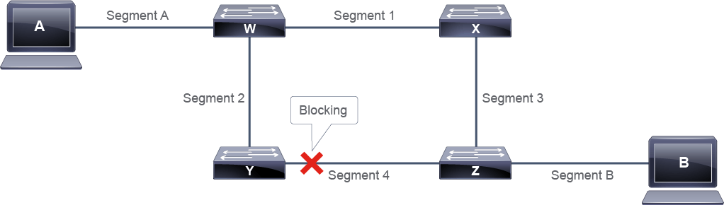
STP behaves in the following way:
STP 的運作方式如下:
- STP uses bridge protocol data units (BPDUs) for communication between switches.STP 使用橋接協定資料單元(BPDU)在交換器之間進行通訊。
- STP forces certain ports into a blocked state so that they do not listen to, forward, or flood data frames. The overall effect is that only one path to each network segment is active at any time.STP 會將某些連接埠強制設為阻斷狀態,使它們不會監聽、轉送或泛流資料框架。整體效果是,任何時間點通往每個網路區段的路徑只有一條處於作用中狀態。
- If there is a connectivity problem with any active network segment, STP activates a previously inactive path, if one exists (changing the blocked port to the forwarding state).如果任何作用中的網路區段發生連線問題,STP 會啟用先前非作用中的路徑(若存在的話),將阻斷的連接埠改為轉送狀態。
To prevent Layer 2 loops in a network, STP uses a reference point called the root bridge. The root bridge is the logical center of the spanning tree topology. All paths that are not needed to reach the root bridge from anywhere in the network are placed in STP blocking mode.
為了防止網路中出現第 2 層迴圈,STP 使用一個稱為根橋接器(root bridge)的參考點。根橋接器是生成樹拓樸的邏輯中心。從網路中任何位置通往根橋接器所不需要的路徑,都會被設為 STP 阻斷模式。
The root bridge is chosen with an election. In the original STP, each switch has a unique 64-bit bridge ID (BID) that consists of the 16-bit bridge priority and 48-bit MAC address as shown in the figure. The bridge priority is a number between 0 and 65535 and the default on Cisco switches is 32768.
根橋接器是透過選舉方式決定的。在原始的 STP 中,每台交換器都有一個獨一無二的 64 位元橋接器 ID(BID),如圖所示,由 16 位元的橋接器優先權與 48 位元的 MAC 位址組成。橋接器優先權是一個介於 0 到 65535 之間的數字,Cisco 交換器的預設值為 32768。

In evolved variants of STP, like Cisco PVST+, RSTP or Multiple Spanning Tree Protocol (MSTP), the original bridge priority field in the BID is changed to include an Extended System ID field as shown in the figure. This field carries information such as VLAN ID or instance number required for the evolved variants of STP to operate. The bridge priority field in this case is 4 bits and the Extended System ID field is 12 bits. In command outputs you will either see this combination written as a 16-bit field, or as two components: a 16-bit bridge priority where the lower 12 bits are binary 0, and a 12-bit Extended System ID. In the latter case, the bridge priority is a number between 0 and 65535 in increments of 4096, and the default on Cisco switches is 32768.
在 Cisco PVST+、RSTP 或多重生成樹協定(MSTP)等演進後的 STP 變體中,BID 中原本的橋接器優先權欄位會改為包含如圖所示的擴充系統 ID(Extended System ID)欄位。此欄位承載 VLAN ID 或執行個體編號等資訊,是這些演進版 STP 運作所需的資訊。在此情況下,橋接器優先權欄位為 4 位元,擴充系統 ID 欄位為 12 位元。在指令輸出中,您可能會看到這個組合被顯示為一個 16 位元欄位,或是兩個部分:一個 16 位元的橋接器優先權(其中較低的 12 位元為二進位 0),以及一個 12 位元的擴充系統 ID。在後者的情況下,橋接器優先權是一個介於 0 到 65535 之間、以 4096 為間隔的數字,Cisco 交換器的預設值為 32768。

The spanning tree algorithm steps are:
生成樹演算法的步驟如下:
- All interfaces on all switches in the spanning tree topology start in blocked mode.生成樹拓樸中所有交換器的所有介面一開始都處於阻斷模式。
- The switches elect a root bridge. The root bridge is selected based on the lowest BID (in all STP variants). If all switches in the network have the same bridge priority, the switch with the lowest MAC address becomes the root bridge. You can only have one root bridge per network in an original STP and one root bridge per VLAN in Cisco PVST+. By default, if a switch that is elected as a root bridge fails, the switch with the next lowest BID becomes the new root bridge. Cisco enables the configuration of a primary and secondary root bridge. If a primary root bridge failure occurs, the configured secondary becomes the new root bridge.交換器會選出一台根橋接器。根橋接器是根據最低的 BID 來選出的(所有 STP 變體皆如此)。如果網路中所有交換器的橋接器優先權都相同,則 MAC 位址最低的交換器會成為根橋接器。在原始 STP 中,每個網路只能有一台根橋接器;在 Cisco PVST+ 中,每個 VLAN 可有一台根橋接器。預設情況下,若被選為根橋接器的交換器故障,BID 次低的交換器會成為新的根橋接器。Cisco 允許設定主要與次要根橋接器。如果主要根橋接器發生故障,設定的次要根橋接器會成為新的根橋接器。
- Each nonroot switch determines a root port. The root port is the port with the best path to the root bridge. The root path cost value is used in this calculation; it is the cumulative STP cost of all links to the root bridge. The root port is the port with the lowest root path cost to the root bridge.每台非根交換器會決定一個根埠(root port)。根埠是通往根橋接器路徑最佳的連接埠。此計算會使用根路徑成本(root path cost)值,也就是通往根橋接器所有鏈路的累計 STP 成本。根埠即為通往根橋接器的根路徑成本最低的連接埠。
- On each segment, a designated port is selected. This is again calculated based on the lowest root path cost. The designated port on a segment is on the switch with the lowest root path cost. On root bridges, all switch ports are designated ports. Each network segment will have one designated port.在每個區段上,會選出一個指定埠(designated port)。這同樣是根據最低的根路徑成本來計算。區段上的指定埠位於根路徑成本最低的交換器上。在根橋接器上,所有交換器連接埠都是指定埠。每個網路區段都會有一個指定埠。
- The root ports and designated ports transition to the forwarding state and any other ports (called nondesignated ports) stay in the blocking state.根埠與指定埠會轉換為轉送狀態,而任何其他連接埠(稱為非指定埠)則會維持在阻斷狀態。
The STP path cost depends on the speed of the link. The first table shows the default STP link costs. The second table shows the summary of the STP port roles.
STP 路徑成本取決於鏈路的速度。第一個表格顯示預設的 STP 鏈路成本,第二個表格則彙整了 STP 連接埠角色。
STP Path Costs
STP 路徑成本
Data Rate 資料速率 | STP Cost (802.1D-1998) STP 成本(802.1D-1998) | STP Cost (802.1D-2004) STP 成本(802.1D-2004) |
4 Mbps 4 Mbps | 250 250 | 5,000,000 5,000,000 |
10 Mbps 10 Mbps | 100 100 | 2,000,000 2,000,000 |
16 Mbps 16 Mbps | 62 62 | 1,250,000 1,250,000 |
100 Mbps 100 Mbps | 19 19 | 200,000 200,000 |
1 Gbps 1 Gbps | 4 4 | 20,000 20,000 |
2 Gbps 2 Gbps | 3 3 | 10,000 10,000 |
10 Gbps 10 Gbps | 2 2 | 2000 2000 |
STP Port Roles
STP 連接埠角色
Port Role 連接埠角色 | Description 說明 |
Root port 根埠 | This port exists on nonroot bridges. It is the switch port with the best path to the root bridge. Root ports forward traffic toward the root bridge and populate the MAC address table for network segments attached to that port. Only one root port is allowed per switch or per VLAN in Cisco PVST+. 此連接埠存在於非根橋接器上,是通往根橋接器路徑最佳的交換器連接埠。根埠會將流量轉送往根橋接器,並為連接在該連接埠上的網路區段填入 MAC 位址表。每台交換器(或在 Cisco PVST+ 中每個 VLAN)只允許有一個根埠。 |
Designated port 指定埠 | This port exists on root and nonroot bridges. For root bridges, all switch ports are designated ports. For nonroot bridges, a designated port is the switch port that will receive and forward frames toward the root bridge as needed. Only one designated port is allowed per segment. If multiple switches exist on the same segment, an election process determines the designated port, and the corresponding switch port begins forwarding frames for the segment. Designated ports populate the MAC address table for the network segment attached to that port. 此連接埠存在於根橋接器與非根橋接器上。對根橋接器而言,所有交換器連接埠都是指定埠。對非根橋接器而言,指定埠是視需要接收並將框架轉送往根橋接器的交換器連接埠。每個區段只允許有一個指定埠。如果同一區段上有多台交換器,會透過選舉程序決定指定埠,對應的交換器連接埠便會開始為該區段轉送框架。指定埠會為連接在該連接埠上的網路區段填入 MAC 位址表。 |
Nondesignated port 非指定埠 | The nondesignated port is a switch port that it is blocking data frames and is not populating the MAC address table with the source addresses of frames that are seen on that segment. 非指定埠是正在阻斷資料框架的交換器連接埠,也不會將該區段上所看到框架的來源位址填入 MAC 位址表。 |
Disabled port 已停用埠 | The disabled port is a switch port that is shut down. 已停用埠是被關閉(shut down)的交換器連接埠。 |
Spanning Tree Operation Example
生成樹運作範例
The first step in the spanning tree algorithm is the election of a root bridge. Initially, all switches assume that they are the root. They start transmitting BPDUs with the Root ID field containing the same value as the bridge ID field. Thus, each switch essentially claims that it is the root bridge on the network.
生成樹演算法的第一步是選舉根橋接器。一開始,所有交換器都假設自己是根。它們開始傳送 BPDU,其中的根 ID(Root ID)欄位值與橋接器 ID 欄位值相同。因此,每台交換器基本上都在宣稱自己是網路上的根橋接器。
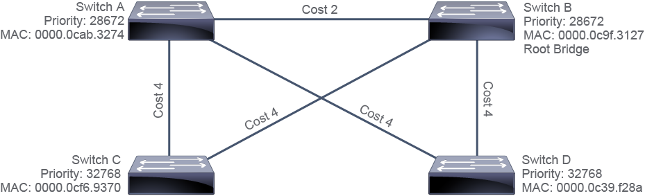
When the switches start receiving BPDUs from the other switches, each switch compares the root ID in the received BPDUs against the value that it currently has recorded as the root ID. If the received value is lower than the recorded value (which was originally the BID of that switch), the switch replaces the recorded value with the received value and starts transmitting this value in the Root ID field in its own BPDUs.
當交換器開始收到其他交換器的 BPDU 時,每台交換器會將收到的 BPDU 中的根 ID 與自己目前記錄的根 ID 值進行比較。如果收到的值低於記錄的值(該記錄值原本是該交換器自身的 BID),交換器就會用收到的值取代記錄值,並開始在自己的 BPDU 中的根 ID 欄位傳送這個新值。
Eventually, all switches learn and record the BID of the switch that has the lowest BID. The switches all transmit this BID in the Root ID field of their BPDUs.
最終,所有交換器都會學習並記錄下 BID 最低的交換器的 BID。所有交換器都會在其 BPDU 的根 ID 欄位中傳送這個 BID。
In the example, Switch B becomes the root bridge because it has the lowest BID. Switch A and Switch B have the same priority, but Switch B has a lower MAC address value.
在這個範例中,交換器 B 因為擁有最低的 BID 而成為根橋接器。交換器 A 與交換器 B 的優先權相同,但交換器 B 的 MAC 位址值較低。
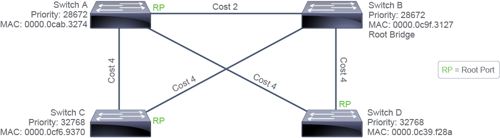
When a switch recognizes that it is not the root (because it is receiving BPDUs that have a root ID value that is lower than its own BID), it marks the port on which it is receiving those BPDUs as its root port.
當交換器發現自己不是根(因為它收到的 BPDU 中根 ID 值低於自身的 BID)時,會將收到這些 BPDU 的連接埠標記為其根埠。
A switch could receive BPDUs on multiple ports. In this case, the switch elects the port that has the lowest-cost path to the root as its root port. If two ports have an equal path cost to the root, the switch looks at the BID values in the received BPDUs to make a decision (where the lowest BID is considered best, similar to root bridge election). If the root path cost and the BID in both BPDUs are the same because both ports are connected to the same upstream switch, the switch looks at the Port ID field in the received BPDUs and selects its root port based on the lowest value in that field.
交換器可能會在多個連接埠上收到 BPDU。在這種情況下,交換器會選擇通往根、成本最低的路徑所在的連接埠作為根埠。如果兩個連接埠通往根的路徑成本相等,交換器會查看收到的 BPDU 中的 BID 值來做決定(BID 越低視為越佳,與根橋接器選舉的邏輯相同)。如果兩個 BPDU 中的根路徑成本與 BID 都相同(因為兩個連接埠都連接到同一台上游交換器),交換器會查看收到的 BPDU 中的連接埠 ID(Port ID)欄位,並根據該欄位中較低的值來選擇根埠。
By default, the cost that is associated with each port is related to its speed (the higher the interface bandwidth, the lower the cost), but the cost can be manually changed.
預設情況下,與每個連接埠相關聯的成本與其速度有關(介面頻寬越高,成本越低),但此成本可以手動變更。
Switches A, C, and D mark the ports that are directly connected to Switch B (which is the root bridge) as the root port. These directly connected ports on switches A, C, and D have the lowest cost to the root bridge.
交換器 A、C、D 會將直接連接到交換器 B(即根橋接器)的連接埠標記為根埠。這些在交換器 A、C、D 上直接連接的連接埠,通往根橋接器的成本最低。
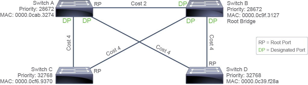
After electing the root bridge and root ports, the switches determine which switch will have the designated port for each Ethernet segment; the switch with the designated port is called the designated bridge for the segment. This process is similar to the root bridge and root port elections. Each switch that is connected to a segment sends BPDUs out of the port that is connected to that segment, claiming to be the designated bridge for that segment. At this point, it considers its port to be a designated port.
在選出根橋接器與根埠之後,交換器會決定哪一台交換器將擁有各個乙太網路區段的指定埠;擁有指定埠的交換器稱為該區段的指定橋接器(designated bridge)。這個過程與根橋接器和根埠的選舉過程類似。每台連接到某區段的交換器都會從連接該區段的連接埠傳送 BPDU,宣稱自己是該區段的指定橋接器。此時,它會將自己的連接埠視為指定埠。
When a switch starts receiving BPDUs from other switches on that segment, it compares the received values of the root path cost, BID, and port ID fields (in that order) against the values in the BPDUs that it is sending out its own port. The switch stops transmitting BPDUs on the port and marks it as a nondesignated port if the other switch has lower values.
當交換器開始從該區段上的其他交換器收到 BPDU 時,它會依序比較收到的根路徑成本、BID 與連接埠 ID 欄位的值,與自己從該連接埠傳送出去的 BPDU 中的值進行比較。如果對方交換器的值較低,該交換器就會停止在該連接埠上傳送 BPDU,並將其標記為非指定埠。
In the example, all ports on the root bridge (Switch B) are designated ports. The ports on Switch A that are connecting to Switch C and Switch D become designated ports, because Switch A has the lower root path cost.
在這個範例中,根橋接器(交換器 B)上的所有連接埠都是指定埠。交換器 A 上連接到交換器 C 與交換器 D 的連接埠會成為指定埠,因為交換器 A 的根路徑成本較低。
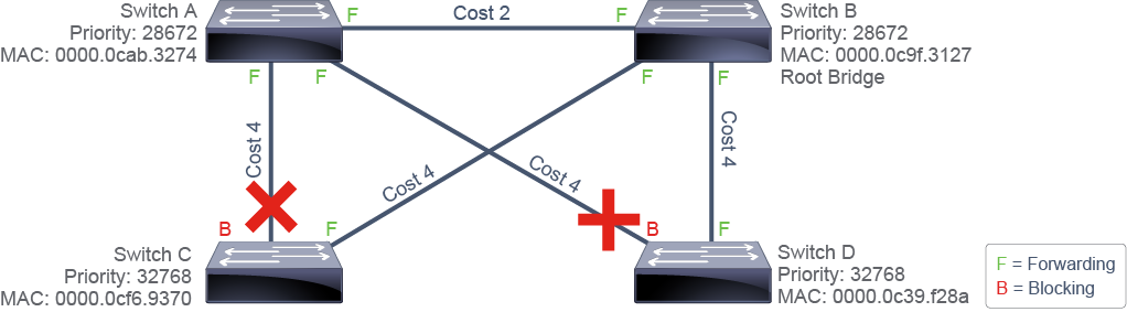
To prevent Layer 2 loops while STP executes its algorithm, all ports start out in the blocking state. When STP marks a port as either a root port or a designated port, the algorithm starts to transition this port to the forwarding state and all nondesignated ports remain in the blocking state.
為了在 STP 執行其演算法期間防止第 2 層迴圈,所有連接埠一開始都處於阻斷狀態。當 STP 將某連接埠標記為根埠或指定埠時,演算法就會開始將該連接埠轉換為轉送狀態,而所有非指定埠則維持在阻斷狀態。
The original and rapid versions of STP both execute the same algorithm in the decision-making process. However, in the transition of a port from the blocking (or discarding, in rapid spanning tree terms) to the forwarding state, there is a big difference between those two spanning tree versions. Classic 802.1D would simply take 30 seconds to transition the port to forwarding. The rapid spanning tree algorithm can use additional mechanisms to transition the port to forwarding in less than a second.
原始版與快速版的 STP 在決策過程中都執行相同的演算法。然而,在連接埠從阻斷(在快速生成樹的術語中稱為丟棄,discarding)轉換為轉送狀態的過程中,這兩個生成樹版本存在很大的差異。傳統的 802.1D 需要花費 30 秒才能將連接埠轉換為轉送狀態。而快速生成樹演算法可以運用額外的機制,在不到一秒的時間內就將連接埠轉換為轉送狀態。
Although the order of the steps that are listed in the diagrams suggests that STP goes through them in a coordinated, sequential manner, that is not actually the case. If you look back at the description of each step in the process, you see that each switch is going through these steps in parallel. Also, each switch might adapt its selection of root bridge, root ports, and designated ports as it receives new BPDUs. As the BPDUs are propagated through the network, all switches eventually have a consistent view of the topology of the network. When this stable state is reached, BPDUs are transmitted only by designated ports. However, all blocking ports are continuously listening for BPDUs that are sent every 2 seconds. If a blocking port stops receiving BPDUs, it will begin transition to the forwarding state.
雖然圖中所列步驟的順序,讓人以為 STP 是以協調、循序的方式逐步進行,但實際情況並非如此。若您回頭檢視流程中每個步驟的描述,會發現每台交換器其實是並行地進行這些步驟。此外,每台交換器可能會隨著收到新的 BPDU,而調整其對根橋接器、根埠與指定埠的選擇。隨著 BPDU 在網路中傳播,所有交換器最終都會對網路拓樸形成一致的認知。當達到這個穩定狀態後,BPDU 就只會由指定埠傳送。然而,所有阻斷中的連接埠仍會持續監聽每 2 秒傳送一次的 BPDU。如果某個阻斷中的連接埠不再收到 BPDU,它就會開始轉換為轉送狀態。
There are two loops in the sample topology, meaning that two ports should be in the blocking state to break both loops. The port on Switch C that is not directly connected to Switch B (root bridge) is blocked, because it is a nondesignated port. The port on Switch D that is not directly connected to Switch B (root bridge) is also blocked, because it is a nondesignated port.
在範例拓樸中有兩個迴圈,這表示需要有兩個連接埠處於阻斷狀態才能打破這兩個迴圈。交換器 C 上未直接連接到交換器 B(根橋接器)的連接埠會被阻斷,因為它是非指定埠。交換器 D 上未直接連接到交換器 B(根橋接器)的連接埠同樣會被阻斷,因為它也是非指定埠。
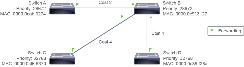
The resulting STP tree can be seen in the preceding figure. STP has its strengths and weaknesses. The strength of STP is that it removes any possible Layer 2 loops found in the topology. However, it does have a weakness, which is that all traffic must traverse the root bridge. If traffic needs to be sent from a source connected to Switch C, to a destination connected to Switch D, traffic will be sent through the root bridge, Switch B. Similar to OSPF, STP trees are considered the shortest path taken in the network. In STP there is only one root and the shortest path is calculated from that device. Meanwhile in OSPF, each router is considered its own root and the Shortest Path First tree is calculated from it. Due to this difference, in STP there is only one tree per topology while in OSPF, there is a tree for each router participating in OSPF in the topology.
最終產生的 STP 樹如上圖所示。STP 有其優點與缺點。STP 的優點在於它能消除拓樸中任何可能存在的第 2 層迴圈。然而它也有一個缺點,就是所有流量都必須經過根橋接器。如果流量需要從連接在交換器 C 上的來源,傳送到連接在交換器 D 上的目的地,該流量將會經由根橋接器(交換器 B)傳送。與 OSPF 類似,STP 樹被視為網路中所走的最短路徑。在 STP 中只有一個根,最短路徑是從該裝置計算出來的。而在 OSPF 中,每台路由器都被視為自己的根,並從該路由器計算出最短路徑優先(Shortest Path First)樹。由於這個差異,STP 中每個拓樸只有一棵樹,而在 OSPF 中,拓樸中每台參與 OSPF 的路由器都各自有一棵樹。