Introduction
簡介
This discovery lab will guide you through the configuration of an interface on a Cisco IOS router. The lab is prepared with the devices represented in the topology diagram and the connectivity table. In general, the devices are fully configured. An exception is an Ethernet0/0 interface on R1. You will configure that interface now.
本探索實驗將引導您完成 Cisco IOS 路由器上介面的設定。此實驗使用拓樸圖與連線表所呈現的裝置進行準備。一般而言,這些裝置都已完成設定,唯一的例外是 R1 上的 Ethernet0/0 介面。您現在將設定該介面。
Topology
拓樸
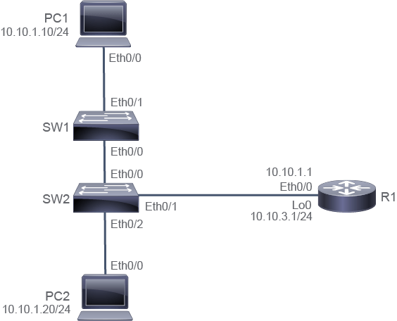
Job Aid
工作輔助資料
Device Information
裝置資訊
Device Information Table
裝置資訊表
Device 裝置 | Characteristic 特性 | Value 值 |
R1 R1 | Ethernet0/0 description Ethernet0/0 描述 | Not configured 尚未設定 |
R1 R1 | Ethernet0/0 IPv4 address Ethernet0/0 IPv4 位址 | Not configured 尚未設定 |
R1 R1 | Loopback 0 IPv4 address Loopback 0 IPv4 位址 | 10.10.3.1/24 10.10.3.1/24 |
PC1 PC1 | IPv4 address IPv4 位址 | 10.10.1.10/24 10.10.1.10/24 |
PC1 PC1 | Default gateway 預設閘道 | 10.10.1.1 10.10.1.1 |
PC2 PC2 | IPv4 address IPv4 位址 | 10.10.1.20/24 10.10.1.20/24 |
PC2 PC2 | Default gateway 預設閘道 | 10.10.1.1 10.10.1.1 |
SW1 SW1 | VLAN 1 IPv4 address VLAN 1 IPv4 位址 | 10.10.1.2/24 10.10.1.2/24 |
SW1 SW1 | Default gateway 預設閘道 | 10.10.1.1 10.10.1.1 |
SW2 SW2 | VLAN 1 IPv4 address VLAN 1 IPv4 位址 | 10.10.1.3/24 10.10.1.3/24 |
SW2 SW2 | Default gateway 預設閘道 | 10.10.1.1 10.10.1.1 |
Task 1: Configure an IPv4 Address on the Router Interfaces
任務 1:在路由器介面上設定 IPv4 位址
Activity
活動
Access the console of R1 and enter the global configuration mode.
存取 R1 的主控台並進入全域設定模式。
On R1, enter the following command:
在 R1 上,輸入以下指令:
R1# configure terminal
Enter configuration commands, one per line.  End with CNTL/Z.
R1(config)#Enter the interface configuration mode for Ethernet0/0, configure 10.10.1.1/24 as its IPv4 address, add an interface description, and then enable the interface.
進入 Ethernet0/0 的介面設定模式,將其 IPv4 位址設定為 10.10.1.1/24,加入介面描述,然後啟用該介面。
On R1, enter the following commands:
在 R1 上,輸入以下指令:
R1(config)# interface Ethernet 0/0
R1(config-if)# ip address 10.10.1.1 255.255.255.0R1(config-if)# description Link to SW2
R1(config-if)# no shutdownExamine the IPv4 routing table on R1. You should see the IPv4 address (L—local) and IPv4 subnet (C—connected) that you have just configured on the Ethernet0/0 interface. When you need to apply a privilege mode command from the configuration mode, an easy way to do it is to add the "do" keyword before your actual command to save your time from going back and forth between the different modes.
檢查 R1 上的 IPv4 路由表。您應該會看到剛才在 Ethernet0/0 介面上設定的 IPv4 位址(L,代表本地)與 IPv4 子網路(C,代表已連接)。當您需要從設定模式套用特權模式指令時,一個簡便的方法是在實際指令前加上「do」關鍵字,省去在不同模式間來回切換的時間。
On R1, enter the following commands:
在 R1 上,輸入以下指令:
R1(config-if)# do show ip route
Codes: L - local, C - connected, S - static, R - RIP, M - mobile, B - BGP
       D - EIGRP, EX - EIGRP external, O - OSPF, IA - OSPF inter area
       N1 - OSPF NSSA external type 1, N2 - OSPF NSSA external type 2
       E1 - OSPF external type 1, E2 - OSPF external type 2
       i - IS-IS, su - IS-IS summary, L1 - IS-IS level-1, L2 - IS-IS level-2
       ia - IS-IS inter area, * - candidate default, U - per-user static route
       o - ODR, P - periodic downloaded static route, H - NHRP, l - LISP
       + - replicated route, % - next hop override

Gateway of last resort is not set

      10.0.0.0/8 is variably subnetted, 4 subnets, 2 masks
C        10.10.1.0/24 is directly connected, Ethernet0/0
L        10.10.1.1/32 is directly connected, Ethernet0/0
C        10.10.3.0/24 is directly connected, Loopback0
L        10.10.3.1/32 is directly connected, Loopback0
In the routing table, the local (L) 10.10.1.1/32 IPv4 address identifies the IPv4 address used on the Ethernet0/0 interface. The connected (C) 10.10.1.0/24 network identifies the network where the Ethernet0/0 interface belongs.
在路由表中,本地(L)10.10.1.1/32 IPv4 位址代表 Ethernet0/0 介面所使用的 IPv4 位址。已連接(C)的 10.10.1.0/24 網路則代表 Ethernet0/0 介面所屬的網路。
Note that there is another pair of C and L entries in the routing table. These are related to the router loopback interface that is preconfigured on the router.
請注意,路由表中還有另一組 C 與 L 項目,這些與路由器上預先設定的回送(loopback)介面有關。
Use the do command to execute an EXEC mode ping command. Attempt to ping PC1 (10.10.1.10). The attempt should succeed.
使用 do 指令執行 EXEC 模式的 ping 指令。嘗試 ping PC1(10.10.1.10)。此嘗試應該會成功。
On R1, enter the following command:
在 R1 上,輸入以下指令:
R1(config-if)# do ping 10.10.1.10
Type escape sequence to abort.
Sending 5, 100-byte ICMP Echos to 10.10.1.10, timeout is 2 seconds:
.!!!!
Success rate is 80 percent (4/5), round-trip min/avg/max = 1/1/1 ms
R1(config-if)#
It is common for the first one or two ICMP echo requests to time out. It is usually due to delays that are associated with updating the ARP cache with the MAC address of the local peer.
前一到兩個 ICMP echo 要求逾時是很常見的情況,這通常是因為更新本地對等端 MAC 位址的 ARP 快取需要一些延遲時間。
Leave the global configuration mode.
離開全域設定模式。
On R1, enter the following command:
在 R1 上,輸入以下指令:
R1(config-if)# end
R1#
Task 2: Verify Interface Configuration and Status
任務 2:驗證介面設定與狀態
Activity
活動
On R1, verify that the running configuration for the Ethernet0/0 interface is correct.
在 R1 上,驗證 Ethernet0/0 介面的執行中設定是否正確。
On R1, enter the following command:
在 R1 上,輸入以下指令:
R1# show running-config interface Ethernet 0/0
Building configuration...

Current configuration : 90 bytes
!
interface Ethernet0/0
 description Link to SW2
 ip address 10.10.1.1 255.255.255.0
end
Router interfaces are "shutdown" by default. If you were to use the show running-config interfaceinterface-id command before enabling the interface, you would see the "shutdown" keyword displayed for the interface. However, when you enable the interface by applying the no shutdown command, you will not see the "no shutdown" keyword when using the show running-config command, as in the example. Commands for some settings are not shown in the output of the show running-config command after you enter them. Certain settings, such as interface administrative status, are considered the default, and they do not appear in the show running-configoutput unless they are changed.
路由器介面預設為「shutdown」狀態。若您在啟用介面之前使用 show running-config interface interface-id 指令,會看到該介面顯示「shutdown」關鍵字。然而,當您透過套用 no shutdown 指令來啟用介面後,如範例所示,使用 show running-config 指令時並不會看到「no shutdown」關鍵字。輸入某些設定的指令後,並不會顯示在 show running-config 指令的輸出中。某些設定(例如介面的管理狀態)被視為預設值,除非經過變更,否則不會出現在 show running-config 的輸出中。
On R1, display a brief summary of the IP information and the statuses of all interfaces.
在 R1 上,顯示所有介面的 IP 資訊摘要與狀態的簡要清單。
On R1, enter the following command:
在 R1 上,輸入以下指令:
R1# show ip interface brief
Interface                  IP-Address      OK? Method Status                Protocol
Ethernet0/0                10.10.1.1       YES manual up                    up
Ethernet0/1                unassigned      YES NVRAM  administratively down down
Ethernet0/2                unassigned      YES NVRAM  administratively down down
Ethernet0/3                unassigned      YES NVRAM  administratively down down
Serial1/0                  unassigned      YES NVRAM  administratively down down
Serial1/1                  unassigned      YES NVRAM  administratively down down
Serial1/2                  unassigned      YES NVRAM  administratively down down
Serial1/3                  unassigned      YES NVRAM  administratively down down
Loopback0                  10.10.3.1       YES NVRAM  up                    up
The Ethernet0/0 interface is configured with the correct IPv4 address. Both the status and the protocol are "up".
Ethernet0/0 介面已設定正確的 IPv4 位址。狀態與通訊協定都是「up」。
On the R1 router, display the status and statistics of the Ethernet0/0 interface.
在 R1 路由器上,顯示 Ethernet0/0 介面的狀態與統計資料。
On R1, enter the following command:
在 R1 上,輸入以下指令:
R1# show interface Ethernet 0/0
Ethernet0/0 is up, line protocol is up
  Hardware is AmdP2, address is aabb.cc00.1800 (bia aabb.cc00.1800) Description: Link to SW2 Internet address is 10.10.1.1/24
  MTU 1500 bytes, BW 10000 Kbit/sec, DLY 1000 usec,
     reliability 255/255, txload 1/255, rxload 1/255
  Encapsulation ARPA, loopback not set
  Keepalive set (10 sec)
  ARP type: ARPA, ARP Timeout 04:00:00
  Last input 00:00:00, output 00:00:06, output hang never
  Last clearing of "show interface" counters never
  Input queue: 0/75/0/0 (size/max/drops/flushes); Total output drops: 0
  Queueing strategy: fifo
  Output queue: 0/40 (size/max)
  5 minute input rate 0 bits/sec, 0 packets/sec
  5 minute output rate 0 bits/sec, 0 packets/sec
     1116 packets input, 71557 bytes, 0 no buffer
     Received 947 broadcasts (0 IP multicasts)
     0 runts, 0 giants, 0 throttles
     0 input errors, 0 CRC, 0 frame, 0 overrun, 0 ignored
     0 input packets with dribble condition detected
     218 packets output, 23872 bytes, 0 underruns
     0 output errors, 0 collisions, 2 interface resets
     3 unknown protocol drops
     0 babbles, 0 late collision, 0 deferred
     0 lost carrier, 0 no carrier
     0 output buffer failures, 0 output buffers swapped out
From the output, you can see that both the status and the protocol for the Ethernet0/0 interface are "up". The interface description is "Link to SW2." 10.10.1.1 is the IPv4 address applied on the interface.
從輸出結果可以看出,Ethernet0/0 介面的狀態與通訊協定都是「up」。介面描述為「Link to SW2」。10.10.1.1 是套用在該介面上的 IPv4 位址。
Which interface status indicates a Layer 2 problem?
哪個介面狀態代表第 2 層的問題?