Introduction
簡介
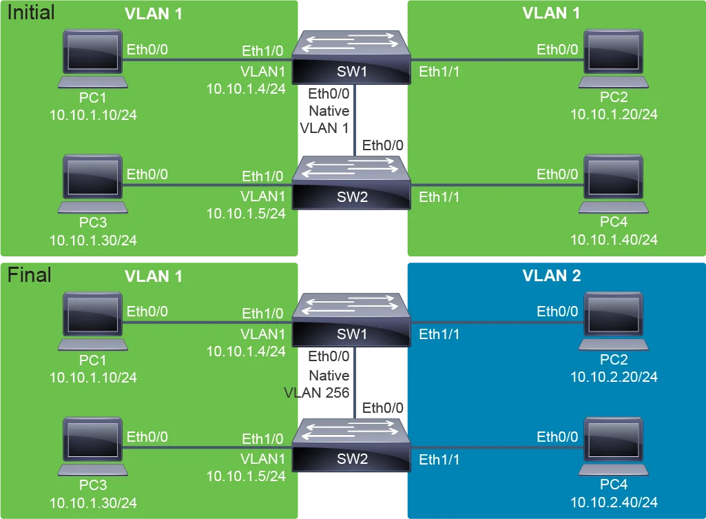
This lab exercise will guide you through several aspects of VLAN operations, including the management of VLANs and using trunks to carry multiple VLANs across a single physical link. When beginning the lab, all devices have IPv4 addresses in the 10.10.1.0/24 subnet. Only the default VLAN, VLAN 1, exists initially. You will start by migrating this configuration to one that uses two VLANs as represented in the topology diagram.
本實驗練習將引導你完成 VLAN 操作的多個層面,包括 VLAN 的管理,以及使用中繼(trunk)在單一實體鏈路上承載多個 VLAN。實驗開始時,所有裝置的 IPv4 位址都在 10.10.1.0/24 子網路中,一開始只存在預設 VLAN(VLAN 1)。你將從這個組態開始,逐步遷移到拓樸圖所示、使用兩個 VLAN 的組態。
Topology
拓樸
Job Aid
輔助資料
Device Information
裝置資訊
Device Information Table
裝置資訊表
Device 裝置 | Characteristic 特性 | Value 值 |
PC1 PC1 | IPv4 address IPv4 位址 | 10.10.1.10/24 10.10.1.10/24 |
PC2 PC2 | IPv4 address IPv4 位址 | 10.10.1.20/24 10.10.1.20/24 |
PC3 PC3 | IPv4 address IPv4 位址 | 10.10.1.30/24 10.10.1.30/24 |
PC4 PC4 | IPv4 address IPv4 位址 | 10.10.1.40/24 10.10.1.40/24 |
SW1 SW1 | VLAN 1 IPv4 Address VLAN 1 IPv4 位址 | 10.10.1.4/24 10.10.1.4/24 |
SW1 SW1 | Ethernet0/0 description Ethernet0/0 描述 | Link to SW2 連往 SW2 的鏈路 |
SW1 SW1 | Ethernet1/0 description Ethernet1/0 描述 | Link to PC1 連往 PC1 的鏈路 |
SW1 SW1 | Ethernet1/1 description Ethernet1/1 描述 | Link to PC2 連往 PC2 的鏈路 |
SW2 SW2 | VLAN 1 IPv4 address VLAN 1 IPv4 位址 | 10.10.1.5/24 10.10.1.5/24 |
SW2 SW2 | Ethernet0/0 description Ethernet0/0 描述 | Link to SW1 連往 SW1 的鏈路 |
SW2 SW2 | Ethernet1/0 description Ethernet1/0 描述 | Link to PC3 連往 PC3 的鏈路 |
SW2 SW2 | Ethernet1/1 description Ethernet1/1 描述 | Link to PC4 連往 PC4 的鏈路 |
Device Information Table (Changes)
裝置資訊表(變更)
Device 裝置 | Characteristic 特性 | Value 值 |
PC2 PC2 | VLAN VLAN | 2 2 |
PC2 PC2 | IPv4 address IPv4 位址 | 10.10.2.20/24 10.10.2.20/24 |
PC4 PC4 | VLAN VLAN | 2 2 |
PC4 PC4 | IPv4 address IPv4 位址 | 10.10.2.40/24 10.10.2.40/24 |
Task 1: Configure VLAN and Trunk
任務 1:配置 VLAN 與中繼
Activity
活動
Start by demonstrating that there is full connectivity between the devices in VLAN 1 on the 10.10.1.0/24 subnet. Access the console of PC1 and ping the IPv4 addresses of the other devices.
首先示範 VLAN 1(10.10.1.0/24 子網路)中的裝置彼此之間有完整的連線能力。存取 PC1 的主控台,並 ping 其他裝置的 IPv4 位址。
Enter the following commands on PC1:
在 PC1 上輸入以下指令:
PC1# ping 10.10.1.20
Type escape sequence to abort.
Sending 5, 100-byte ICMP Echos to 10.10.1.20, timeout is 2 seconds:
.!!!!
Success rate is 80 percent (4/5), round-trip min/avg/max = 1/1/1 ms
PC1# ping 10.10.1.30
Type escape sequence to abort.
Sending 5, 100-byte ICMP Echos to 10.10.1.30, timeout is 2 seconds:
.!!!!
Success rate is 80 percent (4/5), round-trip min/avg/max = 1/1/1 ms
PC1# ping 10.10.1.40
Type escape sequence to abort.
Sending 5, 100-byte ICMP Echos to 10.10.1.40, timeout is 2 seconds:
.!!!!
Success rate is 80 percent (4/5), round-trip min/avg/max = 1/1/1 ms
PC1# ping 10.10.1.4
Type escape sequence to abort.
Sending 5, 100-byte ICMP Echos to 10.10.1.4, timeout is 2 seconds:
.!!!!
Success rate is 80 percent (4/5), round-trip min/avg/max = 1/1/1 ms
PC1# ping 10.10.1.5
Type escape sequence to abort.
Sending 5, 100-byte ICMP Echos to 10.10.1.5, timeout is 2 seconds:
!!!!!
Success rate is 100 percent (5/5), round-trip min/avg/max = 1/1/1 msNow access the console of PC2 and change its IPv4 address to 10.10.2.20 on the 10.10.2.0/24 subnet.
接著存取 PC2 的主控台,將其 IPv4 位址改為 10.10.2.0/24 子網路中的 10.10.2.20。
You can use abbreviated commands during configuration. For example, you can use conf t for configure terminal. If there is any confusion, you can attempt tab completion to expand the full command syntax. For example, conf tab t tab would expand to configure terminal.
設定時你可以使用縮寫指令,例如用 conf t 代表 configure terminal。若不確定完整指令,可以嘗試 Tab 鍵補齊功能展開完整語法。例如 conf tab t tab 會展開為 configure terminal。
Enter the following commands to PC2:
在 PC2 上輸入以下指令:
PC2# configure terminal
Enter configuration commands, one per line.  End with CNTL/Z.
PC2(config)# interface Ethernet0/0
PC2(config-if)# ip address 10.10.2.20 255.255.255.0
PC2(config-if)# end
PC2#
At this point, PC2 is still in VLAN 1, so it is in the same broadcast domain as all the other hosts. But its IPv4 address is configured for a different IPv4 subnet. Therefore, PC2 will not attempt Address Resolution Protocol (ARP) resolution for hosts on the 10.10.1.0/24 subnet. It must use a gateway to reach the 10.10.1.0/24 subnet; however, this gateway does not even exist. PC2 is currently isolated by the IP configuration.
此時 PC2 仍在 VLAN 1 中,因此仍與其他所有主機處於同一廣播網域。但它的 IPv4 位址已設定為不同的 IPv4 子網路,因此 PC2 不會針對 10.10.1.0/24 子網路上的主機嘗試位址解析協定(ARP)解析。它必須透過閘道才能到達 10.10.1.0/24 子網路,但這個閘道根本不存在。PC2 目前因 IP 組態而處於隔離狀態。
Access the console of PC4 and reconfigure its IP address to be 10.10.2.40 on the 10.10.2.0/24 subnet.
存取 PC4 的主控台,將其 IP 位址重新設定為 10.10.2.0/24 子網路中的 10.10.2.40。
Enter the following commands to the PC4:
在 PC4 上輸入以下指令:
PC4# configure terminal
Enter configuration commands, one per line.  End with CNTL/Z.
PC4(config)# interface Ethernet0/0
PC4(config-if)# ip address 10.10.2.40 255.255.255.0
PC4(config-if)# end
PC4#
Now, both PC2 and PC4 are configured for the 10.10.2.0/24 subnet, while the rest of the hosts are configured for the 10.10.1.0/24 subnet. They are all in the same broadcast domain (VLAN 1), but they are isolated by the IP configuration.
現在 PC2 與 PC4 都設定為 10.10.2.0/24 子網路,而其餘主機則設定為 10.10.1.0/24 子網路。它們都在同一個廣播網域(VLAN 1)中,但因 IP 組態而彼此隔離。
Verify that PC4 can communicate with PC2 because they are both configured for the 10.10.2.0/24 subnet. Attempt to ping 10.10.2.20. The ping should succeed.
驗證 PC4 可以與 PC2 通訊,因為兩者都設定在 10.10.2.0/24 子網路中。嘗試 ping 10.10.2.20,這次 ping 應該會成功。
Enter the following commands to PC4:
在 PC4 上輸入以下指令:
PC4# ping 10.10.2.20
Type escape sequence to abort.
Sending 5, 100-byte ICMP Echos to 10.10.2.20, timeout is 2 seconds:
.!!!!
Success rate is 80 percent (4/5), round-trip min/avg/max = 1/1/1 msAccess the console of SW1 and verify that the only Ethernet VLAN is the default VLAN, VLAN 1.
存取 SW1 的主控台,驗證唯一存在的 Ethernet VLAN 是預設 VLAN(VLAN 1)。
Enter the following command to the SW1 switch:
在 SW1 交換器上輸入以下指令:
SW1# show vlan

VLAN Name                             Status    Ports
---- -------------------------------- --------- -------------------------------
1    default                          active    Et0/1, Et0/2, Et0/3, Et1/0
                                                Et1/1, Et1/2, Et1/3
1002 fddi-default                     act/unsup
1003 token-ring-default               act/unsup
1004 fddinet-default                  act/unsup
1005 trnet-default                    act/unsup

VLAN Type  SAID       MTU   Parent RingNo BridgeNo Stp  BrdgMode Trans1 Trans2
---- ----- ---------- ----- ------ ------ -------- ---- -------- ------ ------
1    enet  100001     1500  -      -      -        -    -        0      0
1002 fddi  101002     1500  -      -      -        -    -        0      0
1003 tr    101003     1500  -      -      -        -    -        0      0
1004 fdnet 101004     1500  -      -      -        ieee -        0      0
1005 trnet 101005     1500  -      -      -        ibm  -        0      0

Primary Secondary Type              Ports
------- --------- ----------------- ------------------------------------------
Besides VLAN 1, which is the default Ethernet VLAN, there are four other VLANs that exist by default. VLANs 1002 to 1005 exist to support the legacy Token Ring and FDDI technology. They are very rarely used in networks today.
除了預設 Ethernet VLAN(VLAN 1)之外,還有另外四個預設存在的 VLAN。VLAN 1002 到 1005 是為了支援舊式 Token Ring 與 FDDI 技術而存在,如今在網路中極少使用。
Create VLAN 2 and assign "Engineering" as its name.
建立 VLAN 2,並將其命名為「Engineering」。
Enter the following commands to the SW1 switch:
在 SW1 交換器上輸入以下指令:
SW1# configure terminal
Enter configuration commands, one per line.  End with CNTL/Z.
SW1(config)# vlan 2
SW1(config-vlan)# name Engineering
SW1(config-vlan)# end
SW1#Verify that the VLAN has been created and is active.
驗證該 VLAN 已建立且處於作用中狀態。
Enter the following command to the SW1 switch:
在 SW1 交換器上輸入以下指令:
SW1#show vlan brief

VLAN Name                             Status    Ports
---- -------------------------------- --------- -------------------------------
1    default                          active    Et0/1, Et0/2, Et0/3, Et1/0
                                                Et1/1, Et1/2, Et1/3
2    Engineering                      active
1002 fddi-default                     act/unsup
1003 token-ring-default               act/unsup
1004 fddinet-default                  act/unsup
1005 trnet-default                    act/unsup
You can compare the output of the show vlan brief command to the output of the show vlan command that was used previously. With the brief argument, the characteristics that are only appropriate to Token Ring and FDDI networks (such as parent and ring number) are hidden from the display.
你可以比較 show vlan brief 指令的輸出與先前使用的 show vlan 指令輸出。使用 brief 參數時,僅適用於 Token Ring 與 FDDI 網路的特性(如 parent 與 ring number)會被隱藏,不會顯示出來。
Although VLAN 2 is active, no active ports appear to be using VLAN 2.
雖然 VLAN 2 已處於作用中狀態,但目前似乎沒有任何作用中的連接埠正在使用 VLAN 2。
Look closer at the status of VLAN 2. Display information about it by specifying its VLAN ID in the show vlan idvlan-id command.
進一步查看 VLAN 2 的狀態。透過在 show vlan id vlan-id 指令中指定其 VLAN ID 來顯示相關資訊。
Enter the following command to the SW1 switch:
在 SW1 交換器上輸入以下指令:
SW1# show vlan id 2

VLAN Name                             Status    Ports
---- -------------------------------- --------- -------------------------------
2    Engineering                      active    Et0/0

VLAN Type  SAID       MTU   Parent RingNo BridgeNo Stp  BrdgMode Trans1 Trans2
---- ----- ---------- ----- ------ ------ -------- ---- -------- ------ ------
2    enet  100002     1500  -      -      -        -    -        0      0

Primary Secondary Type              Ports
------- --------- ----------------- ------------------------------------------
When you show all VLANs, only the access mode ports are displayed. When you show a particular VLAN, the trunk ports that carry the VLAN are also displayed. Ethernet0/0 is the trunk port connecting SW1 and SW2.
當你顯示所有 VLAN 時,只會顯示存取模式的連接埠。當你顯示特定 VLAN 時,還會顯示承載該 VLAN 的中繼埠。Ethernet0/0 是連接 SW1 與 SW2 的中繼埠。
In the lab environment, the default trunking encapsulation method on the SW1 and SW2 is Inter-Switch Link (ISL), which is an older Cisco proprietary trunking protocol. IEEE 802.1Q is much more common in networks today, and some switch models no longer support ISL. Thus, before verifying the switch port status of the Ethernet0/0 interface on SW1, explicitly configure this interface to IEEE 802.1Q trunk using the switchport trunk encapsulation dot1q command.
在實驗環境中,SW1 與 SW2 上預設的中繼封裝方式是 Inter-Switch Link(ISL),這是較舊的 Cisco 專有中繼協定。IEEE 802.1Q 在現今網路中更為常見,部分交換器機型甚至已不再支援 ISL。因此,在驗證 SW1 的 Ethernet0/0 介面連接埠狀態之前,先使用 switchport trunk encapsulation dot1q 指令,將此介面明確設定為 IEEE 802.1Q 中繼。
Enter the following commands to the SW1 switch:
在 SW1 交換器上輸入以下指令:
SW1# configure terminal
Enter configuration commands, one per line.  End with CNTL/Z.
SW1(config)# interface Ethernet0/0
SW1(config-if)# switchport trunk encapsulation dot1q
SW1(config-if)# end
SW1#Configure SW2 to be synchronized with the configuration that you just performed on SW1. Access the console of SW2 and configure Ethernet0/0 explicitly as the 802.1Q trunk.
將 SW2 設定為與你剛才在 SW1 上執行的組態同步。存取 SW2 的主控台,將 Ethernet0/0 明確設定為 802.1Q 中繼。
Enter the following commands to the SW2 switch:
在 SW2 交換器上輸入以下指令:
SW2# configure terminal
Enter configuration commands, one per line.  End with CNTL/Z.
SW2(config)# interface Ethernet0/0
SW2(config-if)# switchport trunk encapsulation dot1q
SW2(config-if)# end
SW2#Access the SW1 console and view the switch port status of the Ethernet0/0 interface.
存取 SW1 主控台,檢視 Ethernet0/0 介面的交換器連接埠狀態。
Enter the following command to the SW1 switch:
在 SW1 交換器上輸入以下指令:
SW1# show interface Ethernet0/0 switchport
Name: Et0/0
Switchport: Enabled
Administrative Mode: dynamic desirable
Operational Mode: trunk
Administrative Trunking Encapsulation: dot1q
Operational Trunking Encapsulation: dot1q
Negotiation of Trunking: On
Access Mode VLAN: 1 (default)
Trunking Native Mode VLAN: 1 (default)
Administrative Native VLAN tagging: enabled
Voice VLAN: none
Administrative private-vlan host-association: none
Administrative private-vlan mapping: none
Administrative private-vlan trunk native VLAN: none
Administrative private-vlan trunk Native VLAN tagging: enabled
Administrative private-vlan trunk encapsulation: dot1q
Administrative private-vlan trunk normal VLANs: none
Administrative private-vlan trunk associations: none
Administrative private-vlan trunk mappings: none
Operational private-vlan: none
Trunking VLANs Enabled: ALL
Pruning VLANs Enabled: 2-1001
Capture Mode Disabled
Capture VLANs Allowed: ALL

Appliance trust: none
The default administrative trunking mode on the Ethernet 0/0 switch port on SW1 is "dynamic desirable." Since the other side was able to receive the DTP messages sent from this port, a trunk link was formed between the two switches. Both administrative and operational trunking encapsulations are the 802.1Q trunk. Optionally, you may repeat this verification on SW2.
SW1 上 Ethernet 0/0 交換器連接埠的預設管理中繼模式是「dynamic desirable」。由於對端能夠接收到此連接埠發出的 DTP 訊息,兩台交換器之間便建立了中繼鏈路。管理與運作中繼封裝方式皆為 802.1Q 中繼。你也可以選擇性地在 SW2 上重複這項驗證。
While the trunking status was automatically negotiated between the switches, the best practice is to explicitly configure the trunking status on switch ports. Also, it is best practice to assign a native VLAN to 802.1Q trunks that is not used by any endpoint hosts on the network. Begin this explicit configuration by defining VLAN 256 and assigning it the "NoHosts" name.
雖然中繼狀態是在交換器之間自動協商而成,但最佳實務是在交換器連接埠上明確設定中繼狀態。此外,最佳實務也建議將原生 VLAN 指派為網路中任何終端主機都不使用的 VLAN。先從定義 VLAN 256 並命名為「NoHosts」開始這項明確設定。
Enter the following commands to the SW1 switch:
在 SW1 交換器上輸入以下指令:
SW1# configure terminal
Enter configuration commands, one per line.  End with CNTL/Z.
SW1(config)# vlan 256
SW1(config-vlan)# name NoHosts
SW1(config-vlan)# exit
SW1(config)#
While it makes no difference to the switch which IPv4 subnet you implement on which VLAN, for ease of network management, it is common to use the value of the third octet of the IPv4 network as the VLAN ID, when possible. For example, you would pair VLAN 2 with 10.10.2.0/24, pair VLAN 3 with 10.10.3.0/24, etc.
雖然交換器並不在意你在哪個 VLAN 上實作哪個 IPv4 子網路,但為了方便網路管理,通常會盡可能使用 IPv4 網路第三個八位元組的值作為 VLAN ID。例如,你會將 VLAN 2 與 10.10.2.0/24 配對、VLAN 3 與 10.10.3.0/24 配對,依此類推。
The number 256 is not a valid IPv4 address octet. The X.Y.256.Z addresses are invalid IPv4 addresses. Therefore, 256 can be an effective VID to use for a VLAN that intentionally services no hosts and is used for the native VLAN on 802.1Q trunks.
256 並不是有效的 IPv4 位址八位元組數值,X.Y.256.Z 這類位址屬於無效的 IPv4 位址。因此,256 可以有效地用作 VLAN ID,指定給刻意不服務任何主機、並用於 802.1Q 中繼上原生 VLAN 的 VLAN。
Now, explicitly configure Ethernet0/0 as a trunk using VLAN 256 as the native VLAN.
現在,將 Ethernet0/0 明確設定為以 VLAN 256 作為原生 VLAN 的中繼。
Enter the following commands to the SW1 switch:
在 SW1 交換器上輸入以下指令:
SW1(config)# interface Ethernet0/0
SW1(config-if)# switchport trunk native vlan 256
SW1(config-if)# switchport mode trunk
SW1(config-if)# end
SW1#
Before changing the native VLAN on SW2, you will see on the SW1 console the %CDP-4-NATIVE_VLAN_MISMATCH message every 60 seconds.
在你變更 SW2 上的原生 VLAN 之前,你會看到 SW1 主控台每 60 秒出現一次 %CDP-4-NATIVE_VLAN_MISMATCH 訊息。
*Feb 2 12:34:09.712: %CDP-4-NATIVE_VLAN_MISMATCH: Native VLAN mismatch discovered on Ethernet0/0 (256), with SW2 Ethernet0/0 (1).You must configure SW2 to be synchronized with the configuration that you just performed on SW1. Access the console of SW2, configure VLAN 2 and VLAN 256, and configure Ethernet0/0 explicitly as trunk with VLAN 256 as the native VLAN.
你必須將 SW2 設定為與你剛才在 SW1 上執行的組態同步。存取 SW2 的主控台,設定 VLAN 2 與 VLAN 256,並將 Ethernet0/0 明確設定為以 VLAN 256 作為原生 VLAN 的中繼。
Enter the following commands to the SW2 switch:
在 SW2 交換器上輸入以下指令:
SW2# configure terminal
Enter configuration commands, one per line.  End with CNTL/Z.
SW2(config)# vlan 2
SW2(config-vlan)# name Engineering
SW2(config-vlan)# vlan 256
SW2(config-vlan)# name NoHosts
SW2(config-vlan)# exit
SW2(config)# interface Ethernet0/0
SW2(config-if)# switchport trunk native vlan 256
SW2(config-if)# switchport mode trunk
SW2(config-if)# end
SW2#Verify the trunk status of Ethernet0/0 on SW2.
驗證 SW2 上 Ethernet0/0 的中繼狀態。
Enter the following commands to the SW2 switch:
在 SW2 交換器上輸入以下指令:
SW2# show interface Ethernet0/0 switchport
Name: Et0/0
Switchport: Enabled
Administrative Mode: trunk
Operational Mode: trunk
Administrative Trunking Encapsulation: dot1q
Operational Trunking Encapsulation: dot1q
Negotiation of Trunking: On
Access Mode VLAN: 1 (default)
Trunking Native Mode VLAN: 256 (NoHosts)
Administrative Native VLAN tagging: enabled
Voice VLAN: none
Administrative private-vlan host-association: none
Administrative private-vlan mapping: none
Administrative private-vlan trunk native VLAN: none
Administrative private-vlan trunk Native VLAN tagging: enabled
Administrative private-vlan trunk encapsulation: dot1q
Administrative private-vlan trunk normal VLANs: none
Administrative private-vlan trunk associations: none
Administrative private-vlan trunk mappings: none
Operational private-vlan: none
Trunking VLANs Enabled: ALL
Pruning VLANs Enabled: 2-1001
Capture Mode Disabled
Capture VLANs Allowed: ALL

Appliance trust: none
Both administrative and operational modes are the 802.1Q trunk. The trunking native VLAN is 256. Optionally, you may repeat this verification on SW1.
管理與運作模式皆為 802.1Q 中繼,中繼原生 VLAN 為 256。你也可以選擇性地在 SW1 上重複這項驗證。
VLAN 2 is now ready on both switches, and the trunk link is configured between the two switches. On SW2, explicitly define the PC4 switch port as an access port that is assigned to VLAN 2.
VLAN 2 現在已在兩台交換器上就緒,且兩台交換器之間的中繼鏈路也已設定完成。在 SW2 上,明確將連接 PC4 的交換器連接埠定義為指派給 VLAN 2 的存取埠。
Enter the following commands to the SW2 switch:
在 SW2 交換器上輸入以下指令:
SW2# configure terminal
Enter configuration commands, one per line.  End with CNTL/Z.
SW2(config)# interface Ethernet1/1
SW2(config-if)# switchport access vlan 2
SW2(config-if)# switchport mode access
SW2(config-if)# end
SW2#Verify the status of the Ethernet1/1 switch port configuration.
驗證 Ethernet1/1 交換器連接埠組態的狀態。
Enter the following command to the SW2 switch:
在 SW2 交換器上輸入以下指令:
SW2# show interface Ethernet1/1 switchport
Name: Et1/1
Switchport: Enabled
Administrative Mode: static access
Operational Mode: static access
Administrative Trunking Encapsulation: negotiate
Operational Trunking Encapsulation: native
Negotiation of Trunking: Off
Access Mode VLAN: 2 (Engineering)
Trunking Native Mode VLAN: 1 (default)
Administrative Native VLAN tagging: enabled
Voice VLAN: none
Administrative private-vlan host-association: none
Administrative private-vlan mapping: none
Administrative private-vlan trunk native VLAN: none
Administrative private-vlan trunk Native VLAN tagging: enabled
Administrative private-vlan trunk encapsulation: dot1q
Administrative private-vlan trunk normal VLANs: none
Administrative private-vlan trunk associations: none
Administrative private-vlan trunk mappings: none
Operational private-vlan: none
Trunking VLANs Enabled: ALL
Pruning VLANs Enabled: 2-1001
Capture Mode Disabled
Capture VLANs Allowed: ALL

Appliance trust: noneOn SW2, verify the interface status of the trunk link (Ethernet0/0) and the ports that are supporting PC3 and PC4.
在 SW2 上,驗證中繼鏈路(Ethernet0/0)以及支援 PC3 與 PC4 的連接埠的介面狀態。
Enter the following command to the SW2 switch:
在 SW2 交換器上輸入以下指令:
SW2# show interface status

Port      Name               Status       Vlan       Duplex  Speed Type
Et0/0     Link to SW1        connected    trunk        auto   auto unknown
Et0/1                        connected    1            auto   auto unknown
Et0/2                        connected    1            auto   auto unknown
Et0/3                        connected    1            auto   auto unknown
Et1/0     Link to PC3        connected    1            auto   auto unknown
Et1/1     Link to PC4        connected    2            auto   auto unknown
Et1/2                        connected    1            auto   auto unknown
Et1/3 connected 1 auto auto unknownOn SW1, verify the interface status of the trunk link (Ethernet0/0) and the ports that are supporting PC1 and PC2.
在 SW1 上,驗證中繼鏈路(Ethernet0/0)以及支援 PC1 與 PC2 的連接埠的介面狀態。
Enter the following command to the SW1 switch:
在 SW1 交換器上輸入以下指令:
SW1# show interface status

Port      Name               Status       Vlan       Duplex  Speed Type
Et0/0     Link to SW2        connected    trunk        auto   auto unknown
Et0/1                        connected    1            auto   auto unknown
Et0/2                        connected    1            auto   auto unknown
Et0/3                        connected    1            auto   auto unknown
Et1/0     Link to PC1        connected    1            auto   auto unknown
Et1/1     Link to PC2        connected    1            auto   auto unknown
Et1/2                        connected    1            auto   auto unknown
Et1/3 connected 1 auto auto unknownNotice that PC4 and PC2 are on different VLANs, so although they are configured for the same IPv4 subnet, they should no longer be able to communicate. Verify this status by attempting to ping 10.10.2.20 from PC4. This ping should fail.
注意 PC4 與 PC2 現在位於不同的 VLAN 中,因此儘管它們設定於相同的 IPv4 子網路,也應該無法再互相通訊。請嘗試從 PC4 ping 10.10.2.20 來驗證此狀態,這次 ping 應該會失敗。
Enter the following command to PC4:
在 PC4 上輸入以下指令:
PC4# ping 10.10.2.20
Type escape sequence to abort.
Sending 5, 100-byte ICMP Echos to 10.10.2.20, timeout is 2 seconds:
.....
Success rate is 0 percent (0/5)Access the SW1 console. Configure the switch port connected to PC2 (Ethernet1/1) to be an access port that is assigned to VLAN 2.
存取 SW1 主控台,將連接 PC2 的交換器連接埠(Ethernet1/1)設定為指派給 VLAN 2 的存取埠。
Enter the following commands to the SW1 switch:
在 SW1 交換器上輸入以下指令:
SW1# configure terminal
Enter configuration commands, one per line.  End with CNTL/Z.
SW1(config)# interface Ethernet1/1
SW1(config-if)# switchport access vlan 2
SW1(config-if)# switchport mode access
SW1(config-if)# end
SW1#Verify the switch port status of Ethernet1/1.
驗證 Ethernet1/1 的交換器連接埠狀態。
Enter the following command to the SW1 switch:
在 SW1 交換器上輸入以下指令:
SW1# show interface Ethernet1/1 switchport
Name: Et1/1
Switchport: Enabled
Administrative Mode: static access
Operational Mode: static access
Administrative Trunking Encapsulation: negotiate
Operational Trunking Encapsulation: native
Negotiation of Trunking: Off
Access Mode VLAN: 2 (Engineering)
Trunking Native Mode VLAN: 1 (default)
Administrative Native VLAN tagging: enabled
Voice VLAN: none
Administrative private-vlan host-association: none
Administrative private-vlan mapping: none
Administrative private-vlan trunk native VLAN: none
Administrative private-vlan trunk Native VLAN tagging: enabled
Administrative private-vlan trunk encapsulation: dot1q
Administrative private-vlan trunk normal VLANs: none
Administrative private-vlan trunk associations: none
Administrative private-vlan trunk mappings: none
Operational private-vlan: none
Trunking VLANs Enabled: ALL
Pruning VLANs Enabled: 2-1001
Capture Mode Disabled
Capture VLANs Allowed: ALL

Appliance trust: noneVerify the interface of the SW1 trunk ports and the links to the PCs.
驗證 SW1 中繼埠以及連往 PC 的鏈路的介面狀態。
Enter the following command to the SW1 switch:
在 SW1 交換器上輸入以下指令:
SW1# show interface status

Port      Name               Status       Vlan       Duplex  Speed Type
Et0/0     Link to SW2        connected    trunk        auto   auto unknown
Et0/1                        connected    1            auto   auto unknown
Et0/2                        connected    1            auto   auto unknown
Et0/3                        connected    1            auto   auto unknown
Et1/0     Link to PC1        connected    1            auto   auto unknown
Et1/1     Link to PC2        connected    2            auto   auto unknown
Et1/2                        connected    1            auto   auto unknown
Et1/3 connected 1 auto auto unknownPC2 and PC4 are now both configured for the 10.10.2.0/24 subnet and are in the same broadcast domain (VLAN 2). Access the PC4 console and verify that it can once again ping PC2.
PC2 與 PC4 現在都已設定為 10.10.2.0/24 子網路,並位於同一個廣播網域(VLAN 2)中。存取 PC4 主控台,驗證它是否能再次 ping 通 PC2。
Enter the following command to PC4:
在 PC4 上輸入以下指令:
PC4# ping 10.10.2.20
Type escape sequence to abort.
Sending 5, 100-byte ICMP Echos to 10.10.2.20, timeout is 2 seconds:
!!!!!
Success rate is 100 percent (5/5), round-trip min/avg/max = 1/1/1 msAt this point, there is no routing configured. PC2 and PC4 are isolated from the other hosts that are in VLAN 1. Demonstrate that PC4 cannot ping PC1.
此時尚未設定任何路由。PC2 與 PC4 與 VLAN 1 中的其他主機處於隔離狀態。請示範 PC4 無法 ping 通 PC1。
Enter the following command to PC4:
在 PC4 上輸入以下指令:
PC4# ping 10.10.1.10
Type escape sequence to abort.
Sending 5, 100-byte ICMP Echos to 10.10.1.10, timeout is 2 seconds:
.....
Success rate is 0 percent (0/5)