Introduction
簡介
This activity will guide you through the configuration and verification of OSPF for IPv4 on a Cisco IOS router. The lab is prepared with the devices that are represented in the topology diagram and the connectivity table. All devices have their basic configurations in place, including hostnames and IPv4 addresses. R2 and R3 are also configured with OSPF. You will configure OSPF on R1 and verify the results.
本活動將引導您在 Cisco IOS 路由器上完成 IPv4 版 OSPF 的設定與驗證。實驗環境已依拓樸圖與連線表準備好裝置。所有裝置皆已完成基本設定,包括主機名稱與 IPv4 位址。R2 與 R3 也已設定 OSPF。您將在 R1 上設定 OSPF 並驗證結果。
Topology
拓樸
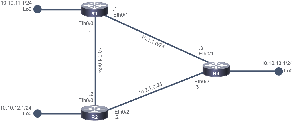
Job Aid
工作輔助資料
The initial configuration is as follows:
初始設定如下:
- All devices have their basic configurations in place, including hostnames and IPv4 addresses.所有裝置皆已完成基本設定,包括主機名稱與 IPv4 位址。
- OSPF is preconfigured on R2 and R3:R2 與 R3 已預先設定 OSPF:
- Process ID number 1 is used.使用處理程序 ID 編號 1。
- Both routers announce a loopback interface network.兩台路由器都宣告一個 Loopback 介面的網路。
Device Information
裝置資訊
Device Details
裝置詳細資料
Device 裝置 | Interface 介面 | IPv4 Address IPv4 位址 | Neighbor 鄰居 |
R1 R1 | Ethernet0/0 Ethernet0/0 | 10.0.1.1/24 10.0.1.1/24 | R2 R2 |
R1 R1 | Ethernet0/1 Ethernet0/1 | 10.1.1.1/24 10.1.1.1/24 | R3 R3 |
R1 R1 | Loopback0 Loopback0 | 10.10.11.1/24 10.10.11.1/24 | " " |
R2 R2 | Ethernet0/0 Ethernet0/0 | 10.0.1.2/24 10.0.1.2/24 | R1 R1 |
R2 R2 | Ethernet0/2 Ethernet0/2 | 10.2.1.2/24 10.2.1.2/24 | R3 R3 |
R2 R2 | Loopback0 Loopback0 | 10.10.12.1/24 10.10.12.1/24 | " " |
R3 R3 | Ethernet0/1 Ethernet0/1 | 10.1.1.3/24 10.1.1.3/24 | R1 R1 |
R3 R3 | Ethernet0/2 Ethernet0/2 | 10.2.1.3/24 10.2.1.3/24 | R2 R2 |
R3 R3 | Loopback0 Loopback0 | 10.10.13.1/24 10.10.13.1/24 | " " |
Command List
指令清單
The table defines the commands that you use to configure OSPF.
此表格說明您用來設定 OSPF 的指令。
Command and Variable 指令與變數 | Description 說明 |
router ospf process-idrouter ospf process-id | Enters the OSPF routing configuration mode. The network administrator chooses the process ID, which is a number between 1 and 65,535. The process ID is locally significant, which means that it does not have to match other OSPF routers to establish adjacencies with those neighbors. 進入 OSPF 路由設定模式。網路管理員自行選擇處理程序 ID,範圍為 1 到 65,535 之間的數字。處理程序 ID 僅具本地意義,也就是說,它不必與其他 OSPF 路由器相符才能與那些鄰居建立鄰接關係。 |
network ip-address wildcard-maskarea area-idnetwork ip-address wildcard-maskarea area-id | Uses a combination of the network address and wildcard mask and serves as the criteria to match when identifying the interfaces that can send and receive OSPF packets. The network address along with the wildcard mask, identifies which networks OSPF will run on, which in turn indicates which networks will be advertised in OSPF. The area ID identifies the OSPF area to which the network belongs. When all the routers are within the same OSPF area, the network commands must be configured with the same area ID on all routers. There must be an Area 0. In a single-area OSPF environment, the area is always 0.結合網路位址與萬用字元遮罩,作為識別可傳送及接收 OSPF 封包之介面的比對條件。網路位址與萬用字元遮罩一起指出 OSPF 將在哪些網路上運作,進而決定哪些網路會被宣告到 OSPF 中。 area ID 用來識別該網路所屬的 OSPF 區域。當所有路由器都在同一個 OSPF 區域內時,各路由器上的 network 指令必須設定相同的 area ID。必須存在 Area 0。在單區域 OSPF 環境中,區域一律為 0。 |
ip ospf process-id area area-idip ospf process-id area area-id | Enables OSPF explicitly on the selected interface. This interface configuration mode command is an alternative to the network command.在所選介面上明確啟用 OSPF。此介面設定模式指令是 network 指令的替代方式。 |
Task 1: Configure and Verify Single-Area OSPF
任務 1:設定與驗證單區域 OSPF
The router ospf command uses a process identifier as an argument. The process ID is a unique, arbitrary number that you select to identify the routing process. The process ID is locally significant and does not need to match the OSPF process ID on other OSPF routers. However, best practice suggests that the process ID should be the same on all routers in the same routing domain.
router ospf 指令使用處理程序識別碼作為引數。處理程序 ID 是您自行選擇、用來識別路由處理程序的唯一任意數字。處理程序 ID 僅具本地意義,不必與其他 OSPF 路由器上的 OSPF 處理程序 ID 相符。不過,最佳實務建議在同一路由網域中的所有路由器上使用相同的處理程序 ID。
The network command identifies which IPv4 networks on the router are part of the OSPF network. For each network, you must also identify the OSPF area to which the networks belong. The network that is identified in the network command does not tell the router which network to advertise; instead, it indicates the interfaces on which OSPF will be enabled. Then, the network configured on these interfaces will be advertised into OSPF.
network 指令用來識別路由器上哪些 IPv4 網路屬於 OSPF 網路。對於每個網路,您也必須識別該網路所屬的 OSPF 區域。network 指令中識別的網路並不是告訴路由器要宣告哪個網路;而是指出要在哪些介面上啟用 OSPF。接著,這些介面上設定的網路就會被宣告到 OSPF 中。
As with subnet mask and an IPv4 address, a wildcard mask is a string of 32 binary digits. However, a wildcard mask is used by a device to determine which bits of the address to examine for a match. A wildcard mask is not used on its own. It is used with an IPv4 address. The matching rule consists of a reference IPv4 address and a wildcard mask that applies to it. When a wildcard mask is applied to the reference IPv4 address, the result is the matching pattern of binary digits. For a match to occur, the IPv4 address from the packet header must match the resulting pattern.
與子網路遮罩和 IPv4 位址相同,萬用字元遮罩也是一串 32 位元的二進位數字。不過,萬用字元遮罩是裝置用來判斷要檢查位址哪些位元以進行比對的依據。萬用字元遮罩不會單獨使用,必須搭配 IPv4 位址一起使用。比對規則由一個參考 IPv4 位址與套用在其上的萬用字元遮罩組成。當萬用字元遮罩套用到參考 IPv4 位址時,結果就是比對用的二進位樣式。若要比對成功,封包標頭中的 IPv4 位址必須符合該樣式。
The wildcard mask bits are used as follows:
萬用字元遮罩位元的使用方式如下:
- Where wildcard mask bit is 0: the value found at the same position in the reference IPv4 address must be matched.當萬用字元遮罩位元為 0 時:必須與參考 IPv4 位址中相同位置的值相符。
- Where wildcard mask bit is 1: the value found at the same position in the reference IPv4 address can be ignored.當萬用字元遮罩位元為 1 時:可以忽略參考 IPv4 位址中相同位置的值。
Activity
活動
Complete the following steps:
完成以下步驟:
Verify the OSPF configuration on router R2 using the show running-config command.
使用 show running-config 指令驗證路由器 R2 上的 OSPF 設定。
On R2, enter the following command:
在 R2 上,輸入以下指令:
R2# show running-config | section ospf
router ospf 1
 router-id 2.2.2.2
 network 10.0.1.0 0.0.0.255 area 0
 network 10.2.1.0 0.0.0.255 area 0
 network 10.10.12.0 0.0.0.255 area 0
You should see that OSPF with the process ID 1 is preconfigured to run on interfaces whose IPv4 address matches the network statements:
您應該可以看到,處理程序 ID 為 1 的 OSPF 已預先設定在 IPv4 位址與 network 陳述式相符的介面上執行:
- Ethernet0/0 (10.0.1.1 matches 10.0.1.0 0.0.0.255 because the first three octets match)Ethernet0/0(10.0.1.1 符合 10.0.1.0 0.0.0.255,因為前三個八位元組相符)
- Ethernet0/2 (10.2.1.2 matches 10.2.1.0 0.0.0.255 because the first three octets match)Ethernet0/2(10.2.1.2 符合 10.2.1.0 0.0.0.255,因為前三個八位元組相符)
- Loopback0 (10.10.12.1 matches 10.10.12.0 0.0.0.255 because the first three octets match)Loopback0(10.10.12.1 符合 10.10.12.0 0.0.0.255,因為前三個八位元組相符)
If you refer to the Job Aids, you can quickly see that the configured OSPF networks are associated with each of the active interfaces on R2. All networks, meaning all active interfaces on the router, belong to the same area—Area 0.
若參閱工作輔助資料,您可以很快看出已設定的 OSPF 網路對應到 R2 上每一個作用中的介面。所有網路(也就是路由器上所有作用中的介面)都屬於同一個區域,即 Area 0。
At this point, note that the router is configured with the router ID 2.2.2.2.
此時請注意,該路由器的路由器 ID 設定為 2.2.2.2。
Another way to verify that the OSPF configuration is by using the show ip protocols command. This command will display the status of the configured dynamic routing protocols on a router. Verify the OSPF configuration on router R3.
另一種驗證 OSPF 設定的方式是使用 show ip protocols 指令。此指令會顯示路由器上已設定的動態路由協定狀態。請驗證路由器 R3 上的 OSPF 設定。
On R3, enter the following command:
在 R3 上,輸入以下指令:
R3# show ip protocols
*** IP Routing is NSF aware ***

Routing Protocol is "ospf 1"
  Outgoing update filter list for all interfaces is not set
  Incoming update filter list for all interfaces is not set
 Router ID 3.3.3.3
  Number of areas in this router is 1. 1 normal 0 stub 0 nssa
  Maximum path: 4
 Routing for Networks:
 10.1.1.0 0.0.0.255 area 0
 10.2.1.0 0.0.0.255 area 0
 10.10.13.0 0.0.0.255 area 0
  Routing Information Sources:
    Gateway         Distance      Last Update
    2.2.2.2              110      17:04:48
  Distance: (default is 110)
You should see that only the OSPF routing protocol is configured on R3. OSPF uses the process ID 1 and is preconfigured to run on interfaces whose IPv4 address matches the network statements:
您應該可以看到 R3 上只設定了 OSPF 這一種路由協定。OSPF 使用處理程序 ID 1,且已預先設定在 IPv4 位址與 network 陳述式相符的介面上執行:
- Ethernet0/1 (10.1.1.3)Ethernet0/1(10.1.1.3)
- Ethernet0/2 (10.2.1.3)Ethernet0/2(10.2.1.3)
- Loopback0 (10.10.13.1)Loopback0(10.10.13.1)
If you refer to the Job Aids, you can see that OSPF on R3 is enabled on all enabled interfaces. All networks, or all interfaces on the router, belong to the same area—Area 0.
若參閱工作輔助資料,您可以看出 R3 上的 OSPF 是在所有已啟用的介面上啟用的。所有網路(也就是路由器上所有介面)都屬於同一個區域,即 Area 0。
The router is preconfigured with the router ID 3.3.3.3.
該路由器已預先設定路由器 ID 為 3.3.3.3。
Router ID
路由器 ID
The OSPF router ID is used to uniquely identify each router in the OSPF routing domain. A router ID is simply a label and is expressed as an IP address. Cisco routers derive the router ID based on three criteria and with this precedence:
OSPF 路由器 ID 用來在 OSPF 路由網域中唯一識別每一台路由器。路由器 ID 只是一個標籤,並以 IP 位址的形式表示。Cisco 路由器依以下三個條件、依此優先順序決定路由器 ID:
- The router uses the IP address (or dotted decimal number) that is configured with the OSPF
router-idcommand.路由器使用透過 OSPFrouter-id指令設定的 IP 位址(或點分十進位數字)。 - If the router ID is not configured, the router chooses the highest IP address from its loopback interfaces.若未設定路由器 ID,路由器會從其 Loopback 介面中選擇最高的 IP 位址。
- If no loopback interfaces are configured, the router chooses the highest active IP address from its physical interfaces.若未設定任何 Loopback 介面,路由器會從其實體介面中選擇最高的作用中 IP 位址。
If an OSPF router is not configured with an OSPF router-id command and no loopback interfaces with IPv4 addresses are configured, then the OSPF router ID will be the highest IPv4 address on any of its active interfaces. The interface does not need to be enabled for OSPF, meaning that it does not need to be included in one of the OSPF network commands. However, the interface must be active—it must be in the "up" state.
若 OSPF 路由器未設定 OSPF router-id 指令,且也未設定任何具有 IPv4 位址的 Loopback 介面,則 OSPF 路由器 ID 會是其任一作用中介面上最高的 IPv4 位址。該介面不需要已啟用 OSPF,也就是說,它不需要包含在任何 OSPF network 指令中。不過,該介面必須是作用中的,也就是必須處於「up」狀態。
On R1, you should configure OSPF process ID 1. Configure the router ID to 1.1.1.1. Include all the networks that are associated with each of the three active interfaces for R1 in Area 0.
在 R1 上,您應設定 OSPF 處理程序 ID 1。將路由器 ID 設為 1.1.1.1。將 R1 三個作用中介面所對應的所有網路都納入 Area 0。
On R1, enter the following commands:
在 R1 上,輸入以下指令:
R1# configure terminal
R1(config)# router ospf 1
R1(config-router)# router-id 1.1.1.1
R1(config-router)# network 10.0.1.0 0.0.0.255 area 0
R1(config-router)# network 10.1.1.0 0.0.0.255 area 0
R1(config-router)# network 10.10.11.0 0.0.0.255 area 0R1(config-router)# end
During configuration, a syslog message indicates that new adjacencies have been initiated with two neighbors, R2 and R3. The OSPF neighbor state is "FULL", which means that they have synchronized to each other and share the same LSDB knowledge. Note that R2 and R3 are represented by the preconfigured router IDs, 2.2.2.2 and 3.3.3.3, respectively.
在設定過程中,系統日誌訊息會顯示已與兩個鄰居 R2 和 R3 啟動新的鄰接關係。OSPF 鄰居狀態為「FULL」,表示彼此已完成同步,並共享相同的 LSDB 資訊。請注意,R2 和 R3 分別以預先設定的路由器 ID 2.2.2.2 和 3.3.3.3 表示。
*Oct 13 07:24:35.278: %OSPF-5-ADJCHG: Process 1, Nbr 2.2.2.2 on Ethernet0/0 from LOADING to FULL, Loading Done
*Oct 13 07:24:46.037: %OSPF-5-ADJCHG: Process 1, Nbr 3.3.3.3 on Ethernet0/1 from LOADING to FULL, Loading Done.
Verify Single-Area OSPF
驗證單區域 OSPF
You can use several commands to verify the configuration of single-area OSPF:
您可以使用多個指令來驗證單區域 OSPF 的設定:
- Router#
show ip ospf interface briefRouter#show ip ospf interface briefThe
show ip ospf interface briefcommand verifies the interfaces that are enabled for OSPF. It is useful to determine if yournetworkstatements are correctly configured.show ip ospf interface brief指令用來驗證哪些介面已啟用 OSPF。這對判斷您的network陳述式是否正確設定很有用。 - Router#
show ip ospf interfaceinterface-idRouter#show ip ospf interfaceinterface-idThe
show ip ospf interfaceinterface-id command verifies all OSPF-related configuration on an interface.show ip ospf interfaceinterface-id 指令用來驗證某介面上所有與 OSPF 相關的設定。 - Router#
show ip protocolsRouter#show ip protocolsThe
show ip protocolscommand provides a summary of the configured routing protocol information. You can see the protocols that are enabled and the networks that these protocols are routing for. You can also see on which interfaces the routing protocols were enabled explicitly.show ip protocols指令提供已設定路由協定資訊的摘要。您可以看到哪些協定已啟用,以及這些協定正在為哪些網路進行路由。您也可以看到路由協定是在哪些介面上明確啟用的。 - Router#
show ip ospf neighborRouter#show ip ospf neighborThe
show ip ospf neighborcommand displays the OSPF neighbor information on a per-interface basis.show ip ospf neighbor指令會依每個介面顯示 OSPF 鄰居資訊。 - Router#
show ip routeRouter#show ip routeThe
show ip routecommand displays the routes that are known to the router and how they are learned. This command is one of the best ways to determine connectivity between the local router and the rest of the internetwork.show ip route指令會顯示路由器所知道的路由,以及這些路由的學習方式。此指令是判斷本地路由器與其餘網際網路連線狀況最好的方法之一。
Display the interfaces on R1 that are participating in OSPF.
顯示 R1 上參與 OSPF 的介面。
On R1, enter the following command:
在 R1 上,輸入以下指令:
R1# show ip ospf interface brief
Interface    PID   Area            IP Address/Mask    Cost  State Nbrs F/C
Lo0 1 0               10.10.11.1/24      1     P2P  0/0
Et0/1 1 0               10.1.1.1/24        10    BDR   1/1
Et0/0 1 0               10.0.1.1/24        10    BDR   1/1
Ethernet0/0, Ethernet0/1, and Loopback0 are participating in OSPF in Area 0, under process ID 1 and belong to Area 0. The cost on Ethernet0/0 and Ethernet0/1 interfaces is 10, because they both are Ethernet interfaces, while the Loopback0 interface has a cost of 1. By default, the cost on loopback interfaces is set to 1.
Ethernet0/0、Ethernet0/1 和 Loopback0 皆在處理程序 ID 1 下參與 OSPF,並屬於 Area 0。Ethernet0/0 與 Ethernet0/1 介面的成本皆為 10,因為兩者都是 Ethernet 介面,而 Loopback0 介面的成本為 1。依預設,Loopback 介面的成本設為 1。
Hello and dead intervals
Hello 與 dead 間隔
The hello interval specifies the frequency in seconds at which a router sends hello packets. The default hello interval on multiaccess networks is 10 seconds. The dead interval is the time in seconds that a router waits to hear from a neighbor before declaring the neighboring router out of service. By default, the dead interval is four times the hello interval. These timers must be the same on neighboring routers; otherwise, an adjacency will not be established.
hello 間隔指定路由器傳送 hello 封包的頻率(以秒為單位)。在多重存取網路上,預設的 hello 間隔為 10 秒。dead 間隔是路由器在宣告鄰居路由器失效之前,等待該鄰居訊息的時間(以秒為單位)。依預設,dead 間隔是 hello 間隔的四倍。這些計時器在鄰近的路由器上必須相同,否則將無法建立鄰接關係。
Display detailed information about the interfaces on R1 that are participating in OSPF.
顯示 R1 上參與 OSPF 之介面的詳細資訊。
On R1, enter the following command:
在 R1 上,輸入以下指令:
R1# show ip ospf interface
Loopback0 is up, line protocol is up
  Internet Address 10.10.11.1/24, Area 0, Attached via Network Statement
 Process ID 1, Router ID 1.1.1.1, Network Type POINT_TO_POINT, Cost: 1
  Topology-MTID    Cost    Disabled    Shutdown      Topology Name
        0           1         no          no            Base
  Transmit Delay is 1 sec, State POINT_TO_POINT
 Timer intervals configured, Hello 10, Dead 40, Wait 40, Retransmit 5
    oob-resync timeout 40
  <--- output omitted --->
Ethernet0/1 is up, line protocol is up
  Internet Address 10.1.1.1/24, Area 0, Attached via Network Statement
  Process ID 1, Router ID 1.1.1.1, Network Type BROADCAST, Cost: 10
  Topology-MTID    Cost    Disabled    Shutdown      Topology Name
        0           10        no          no            Base
  Transmit Delay is 1 sec, State BDR, Priority 1
  <--- output omitted --->
Ethernet0/0 is up, line protocol is up
  Internet Address 10.0.1.1/24, Area 0, Attached via Network Statement
  Process ID 1, Router ID 1.1.1.1, Network Type BROADCAST, Cost: 10
  Topology-MTID    Cost    Disabled    Shutdown      Topology Name
        0           10        no          no            Base
  Transmit Delay is 1 sec, State BDR, Priority 1
  Designated Router (ID) 2.2.2.2, Interface address 10.0.1.2
  Backup Designated router (ID) 1.1.1.1, Interface address 10.0.1.1
 <--- output omitted --->
The output of this command provides many details about all interfaces on the router that participate in OSPF. Ethernet0/0, Ethernet0/1, and Loopback 0 interfaces are all active (status and line protocol is "up") and belong to OSPF area 0. They share the same information about the process ID and router ID, which is 1 and 1.1.1.1, respectively. The cost for the loopback 0 interface is 1, while the cost for each Ethernet interface is 10.
此指令的輸出提供了路由器上所有參與 OSPF 之介面的許多詳細資訊。Ethernet0/0、Ethernet0/1 和 Loopback0 介面皆為作用中(狀態與線路協定皆為「up」),並屬於 OSPF 的 Area 0。它們共享相同的處理程序 ID 與路由器 ID 資訊,分別為 1 和 1.1.1.1。Loopback0 介面的成本為 1,而每個 Ethernet 介面的成本為 10。
The output of this command also provides information about OSPF timers. On these interfaces the hello interval has a default value of 10 seconds and the dead interval also has a default value of 40 seconds.
此指令的輸出也提供了 OSPF 計時器的資訊。在這些介面上,hello 間隔的預設值為 10 秒,dead 間隔的預設值也為 40 秒。
Verify the OSPF configuration on R1.
驗證 R1 上的 OSPF 設定。
On R1, enter the following command:
在 R1 上,輸入以下指令:
R1# show ip protocols
*** IP Routing is NSF aware ***

Routing Protocol is "ospf 1"
  Outgoing update filter list for all interfaces is not set
  Incoming update filter list for all interfaces is not set
 Router ID 1.1.1.1
  Number of areas in this router is 1. 1 normal 0 stub 0 nssa
  Maximum path: 4
 Routing for Networks:
    10.0.1.0 0.0.0.255 area 0
    10.1.1.0 0.0.0.255 area 0
    10.10.11.0 0.0.0.255 area 0
  Routing Information Sources:
 Gateway         Distance      Last Update
 2.2.2.2              110      00:02:46
 3.3.3.3              110      00:02:36
  Distance: (default is 110)
You should see only OSPF configuration because OSPF is the only routing protocol that is running on R1. The router ID is 1.1.1.1. OSPF uses process ID 1 and is configured to run on the interfaces whose IPv4 address matches the network statements:
您應該只會看到 OSPF 設定,因為 OSPF 是 R1 上唯一執行的路由協定。路由器 ID 為 1.1.1.1。OSPF 使用處理程序 ID 1,並設定為在 IPv4 位址與 network 陳述式相符的介面上執行:
- Ethernet0/0 (10.0.1.1)Ethernet0/0(10.0.1.1)
- Ethernet0/1 (10.1.1.1)Ethernet0/1(10.1.1.1)
- Loopback0 (10.10.11.1)Loopback0(10.10.11.1)
All three interfaces participate in the same OSPF area 0.
三個介面都參與同一個 OSPF Area 0。
In addition to all that information, the show ip protocols command also provides information about the OSPF neighbors, which are identified in the Gateway column. 2.2.2.2 and 3.3.3.3 are the router IDs of R2 and R3, respectively.
除了上述所有資訊之外,show ip protocols 指令還會提供關於 OSPF 鄰居的資訊,這些鄰居會列在 Gateway 欄位中。2.2.2.2 和 3.3.3.3 分別是 R2 和 R3 的路由器 ID。
Display the list of the OSPF neighbors for R1.
顯示 R1 的 OSPF 鄰居清單。
On R1, enter the following command:
在 R1 上,輸入以下指令:
R1# show ip ospf neighbor

Neighbor ID     Pri   State           Dead Time   Address         Interface
3.3.3.3           1   FULL/DR         00:00:38    10.1.1.3 Ethernet0/1
2.2.2.2           1   FULL/DR         00:00:34    10.0.1.2 Ethernet0/0
R1 has two neighbors:
R1 有兩個鄰居:
- 3.3.3.3 (router ID of R3), which can be reached via the Ethernet0/1 interface. The 10.1.1.3 IPv4 address is used on the R3 interface to which R1 directly connects.3.3.3.3(R3 的路由器 ID),可透過 Ethernet0/1 介面到達。R1 直接連接的 R3 介面使用 10.1.1.3 這個 IPv4 位址。
- 2.2.2.2 (router ID of R2), which can be reached via the Ethernet0/0 interface. The 10.0.1.2 IPv4 address is used on the R2 interface to which R1 directly connects.2.2.2.2(R2 的路由器 ID),可透過 Ethernet0/0 介面到達。R1 直接連接的 R2 介面使用 10.0.1.2 這個 IPv4 位址。
Notice that the neighbor state is "FULL/DR" indicating that the OSPF adjacency is established and both of the neighbors are DR routers on the link with R1. Instead of DR, you could also see a BDR state, indicating that the router is BDR or DROTHER. DROTHER would indicate that the router is neither the DR nor the BDR. A router could be DROTHER either because other routers are DR and BDR (on a LAN with more than two routers) or because the router has its priority set to 0 and therefore it cannot become the DR or BDR.
請注意,鄰居狀態為「FULL/DR」,表示 OSPF 鄰接關係已建立,且這兩個鄰居在與 R1 相連的鏈路上都是 DR 路由器。除了 DR 之外,您也可能會看到 BDR 狀態,表示該路由器是 BDR 或 DROTHER。DROTHER 表示該路由器既不是 DR 也不是 BDR。路由器會成為 DROTHER,可能是因為其他路由器已是 DR 與 BDR(在有兩台以上路由器的 LAN 上),也可能是因為該路由器的優先權設為 0,因此無法成為 DR 或 BDR。
On R2, display the list of the OSPF neighbors to verify that the neighbor state of R1 is BDR.
在 R2 上,顯示 OSPF 鄰居清單,以驗證 R1 的鄰居狀態為 BDR。
On R2, enter the following command:
在 R2 上,輸入以下指令:
R2# show ip ospf neighbor

Neighbor ID     Pri   State           Dead Time   Address         Interface
3.3.3.3           1   FULL/DR         00:00:38    10.2.1.3        Ethernet0/2
1.1.1.1           1   FULL/BDR        00:00:39    10.0.1.1        Ethernet0/0
Notice that the neighbor state for R1 (router ID 1.1.1.1) is "FULL/BDR," indicating that the OSPF adjacency is established and R1 is the BDR router on the link with R2.
請注意,R1(路由器 ID 1.1.1.1)的鄰居狀態為「FULL/BDR」,表示 OSPF 鄰接關係已建立,且 R1 是與 R2 相連鏈路上的 BDR 路由器。
You can also use the same show ip ospf neighbor command on R3 to verify that R1 is BDR router on the link with R3.
您也可以在 R3 上使用相同的 show ip ospf neighbor 指令,驗證 R1 是與 R3 相連鏈路上的 BDR 路由器。
Display the routing table on R1.
顯示 R1 的路由表。
On R1, enter the following command:
在 R1 上,輸入以下指令:
R1# show ip route
Codes: L - local, C - connected, S - static, R - RIP, M - mobile, B - BGP
       D - EIGRP, EX - EIGRP external, O - OSPF, IA - OSPF inter area
       N1 - OSPF NSSA external type 1, N2 - OSPF NSSA external type 2
       E1 - OSPF external type 1, E2 - OSPF external type 2
       i - IS-IS, su - IS-IS summary, L1 - IS-IS level-1, L2 - IS-IS level-2
       ia - IS-IS inter area, * - candidate default, U - per-user static route
       o - ODR, P - periodic downloaded static route, H - NHRP, l - LISP
       + - replicated route, % - next hop override

Gateway of last resort is not set

      10.0.0.0/8 is variably subnetted, 9 subnets, 2 masks
C        10.0.1.0/24 is directly connected, Ethernet0/0
L        10.0.1.1/32 is directly connected, Ethernet0/0
C        10.1.1.0/24 is directly connected, Ethernet0/1
L        10.1.1.1/32 is directly connected, Ethernet0/1
O        10.2.1.0/24 [110/20] via 10.1.1.3, 00:04:50, Ethernet0/1
                     [110/20] via 10.0.1.2, 00:05:00, Ethernet0/0
C        10.10.11.0/24 is directly connected, Loopback0
L        10.10.11.1/32 is directly connected, Loopback0
O        10.10.12.0/24 [110/11] via 10.0.1.2, 00:05:00, Ethernet0/0
O        10.10.13.0/24 [110/11] via 10.1.1.3, 00:04:50, Ethernet0/1
The routes that the router has learned via OSPF are tagged with an "O".
路由器透過 OSPF 學習到的路由,會標示為「O」。
R1 has learned the following networks:
R1 已學習到以下網路:
- The network between R2 and R3 that has two equal cost paths—via the Ethernet0/0 and Ethernet0/1 interfaces. For both routes to 10.2.1.0/24 network, the parameters in the square brackets are the same. The first parameter has value of 110 and identifies the administrative distance for OSPF, while the second parameter has value of 20 and identifies the total cost of the path. Because both paths are equally good (they have the same cost), they are both included in the routing table and used by R1 when sending traffic to 10.2.1.0/24 network. R1 will send packets on either path; this is called load-balancing.R2 與 R3 之間的網路有兩條成本相同的路徑,分別經由 Ethernet0/0 與 Ethernet0/1 介面。對於通往 10.2.1.0/24 網路的這兩條路由,方括號中的參數皆相同。第一個參數值為 110,代表 OSPF 的管理距離;第二個參數值為 20,代表該路徑的總成本。由於兩條路徑成本相同(同樣優良),因此兩者都會列入路由表,並由 R1 用來將流量傳送至 10.2.1.0/24 網路。R1 會在任一路徑上傳送封包,這稱為負載平衡。
- The network of the loopback interface on R2; best path is via Ethernet0/0R2 上 Loopback 介面所屬的網路;最佳路徑經由 Ethernet0/0
- The network of the loopback interface on R3; best path is via Ethernet0/1R3 上 Loopback 介面所屬的網路;最佳路徑經由 Ethernet0/1
OSPF Metric
OSPF 度量值
You can apply realistic cost, influencing the following:
您可以套用符合實際情況的成本,影響以下項目:
- Reference bandwidth, by using the ospf auto-cost reference bandwidth reference-bandwidth command參考頻寬,使用 ospf auto-cost reference bandwidth reference-bandwidth 指令
- Interface cost, by using the ip ospf cost cost command介面成本,使用 ip ospf cost cost 指令
- Interface bandwidth, by using the bandwidth command介面頻寬,使用 bandwidth 指令
R1 has two paths to the 10.2.1.0/24 network, because both paths have equal costs. Influence the interface cost on R1 so that only the path via Ethernet0/0 will be chosen as the best one. Use 1 as the cost parameter.
R1 有兩條通往 10.2.1.0/24 網路的路徑,因為兩條路徑的成本相同。請調整 R1 上的介面成本,使得只有經由 Ethernet0/0 的路徑會被選為最佳路徑。成本參數請使用 1。
First, verify the costs of the Ethernet0/0 and Ethernet0/1 interfaces.
首先,驗證 Ethernet0/0 與 Ethernet0/1 介面的成本。
R1# show ip ospf interface brief
Interface    PID   Area            IP Address/Mask    Cost  State Nbrs F/C
Lo0          1     0               10.10.11.1/24      1     LOOP  0/0
Et0/1        1     0               10.1.1.1/24        10    BDR   1/1
Et0/0        1     0               10.0.1.1/24        10    BDR   1/1
Both interfaces have the same cost"10. If you want the path via Ethernet0/0 to be chosen, you have to change its cost to a lower value.
兩個介面的成本相同,皆為 10。若您希望選擇經由 Ethernet0/0 的路徑,就必須將其成本改為較低的值。
R1# configure terminal
R1(config)# interface Ethernet0/0
R1(config-if)# ip ospf cost 1R1(config-if)# end
Alternatively, you could also change the cost of Ethernet0/1 to a higher value.
或者,您也可以改為將 Ethernet0/1 的成本調高。
Again, display the routing table of R1. Verify that there is only one path, the path via Ethernet0/0, to reach the 10.2.1.0/24 network.
再次顯示 R1 的路由表。驗證只剩下一條路徑,也就是經由 Ethernet0/0 的路徑,可用來到達 10.2.1.0/24 網路。
On R1, enter the following command:
在 R1 上,輸入以下指令:
R1# show ip route
Codes: L - local, C - connected, S - static, R - RIP, M - mobile, B - BGP
       D - EIGRP, EX - EIGRP external, O - OSPF, IA - OSPF inter area
       N1 - OSPF NSSA external type 1, N2 - OSPF NSSA external type 2
       E1 - OSPF external type 1, E2 - OSPF external type 2
       i - IS-IS, su - IS-IS summary, L1 - IS-IS level-1, L2 - IS-IS level-2
       ia - IS-IS inter area, * - candidate default, U - per-user static route
       o - ODR, P - periodic downloaded static route, H - NHRP, l - LISP
       + - replicated route, % - next hop override

Gateway of last resort is not set

      10.0.0.0/8 is variably subnetted, 9 subnets, 2 masks
C        10.0.1.0/24 is directly connected, Ethernet0/0
L        10.0.1.1/32 is directly connected, Ethernet0/0
C        10.1.1.0/24 is directly connected, Ethernet0/1
L        10.1.1.1/32 is directly connected, Ethernet0/1
O        10.2.1.0/24 [110/11] via 10.0.1.2, 00:00:02, Ethernet0/0
C        10.10.11.0/24 is directly connected, Loopback0
L        10.10.11.1/32 is directly connected, Loopback0
O        10.10.12.0/24 [110/2] via 10.0.1.2, 00:00:02, Ethernet0/0
O        10.10.13.0/24 [110/11] via 10.1.1.3, 00:06:44, Ethernet0/1
The total cost to reach the 10.2.1.0/24 network is 11, which is the sum of the costs on all the links to reach the network (including the cost of the links that R2 needs to reach this network).
到達 10.2.1.0/24 網路的總成本為 11,也就是到達該網路所經過所有鏈路成本的總和(包含 R2 到達該網路所需的鏈路成本)。
- R1 can reach this network via R2. The cost of the link for R1 to reach R2 is 1 (the cost that you configured).R1 可透過 R2 到達此網路。R1 到達 R2 的鏈路成本為 1(您所設定的成本)。
- The cost of the link for R2 to reach the 10.2.1.0/24 network is 10.R2 到達 10.2.1.0/24 網路的鏈路成本為 10。
Passive Interfaces in OSPF
OSPF 中的被動介面
With OSPF running on a network, the passive-interface command stops both outgoing and incoming routing updates because the effect of the command causes the router to stop sending and receiving hello packets over an interface. For this reason, the routers will not become neighbors. Use the passive interface configuration only on the interfaces where you do not expect the router to form any OSPF neighbor adjacency, for example on a connection to an end device.
在網路上執行 OSPF 時,passive-interface 指令會停止傳出與傳入的路由更新,因為此指令的效果是讓路由器停止透過該介面傳送與接收 hello 封包。因此,這些路由器不會成為鄰居。只有在您不希望路由器與其形成任何 OSPF 鄰居鄰接關係的介面上(例如連接終端裝置的連線),才使用被動介面設定。
You can configure either a specific interface as passive or you can turn on a passive interface setting as the default, changing all interfaces to passive for OSPF, and then make active for OSPF the interfaces that should not be configured as passive with the no passive-interface configuration command.
您可以將特定介面設定為被動介面,也可以將被動介面設定為預設值,將所有介面都改為 OSPF 被動,再使用 no passive-interface 設定指令,將不應設為被動的介面改為 OSPF 作用中介面。
On R1, set all interfaces as passive except the interface that connects to R3. The easiest way is to use the passive-interface default command.
在 R1 上,將除了連接 R3 的介面之外的所有介面都設為被動。最簡單的方式是使用 passive-interface default 指令。
On R1, enter the following commands:
在 R1 上,輸入以下指令:
R1# configure terminal
R1(config)# router ospf 1
R1(config-router)# passive-interface default
*Oct 13 11:30:01.326: %OSPF-5-ADJCHG: Process 1, Nbr 2.2.2.2 on Ethernet0/0 from FULL to DOWN, Neighbor Down: Interface down or detached
*Oct 13 11:30:01.326: %OSPF-5-ADJCHG: Process 1, Nbr 3.3.3.3 on Ethernet0/1 from FULL to DOWN, Neighbor Down: Interface down or detached
R1(config-router)# no passive-interface Ethernet0/1
*Oct 13 11:31:07.174: %OSPF-5-ADJCHG: Process 1, Nbr 3.3.3.3 on Ethernet0/1 from LOADING to FULL, Loading DoneR1(config-router)# end
Note that during configuration, a syslog message indicates that existing adjacencies have been terminated. After you specify that Ethernet0/1 should not be configured as passive, the new adjacency is initiated with R3.
請注意,在設定過程中,系統日誌訊息會顯示現有的鄰接關係已終止。在您指定 Ethernet0/1 不應設為被動之後,會與 R3 啟動新的鄰接關係。
Display the list of the OSPF neighbors on R1.
顯示 R1 上的 OSPF 鄰居清單。
On R1, enter the following command:
在 R1 上,輸入以下指令:
R1# show ip ospf neighbor

Neighbor ID     Pri   State           Dead Time   Address         Interface
3.3.3.3           1   FULL/DR         00:00:31    10.1.1.3        Ethernet0/1
Because only Ethernet0/1 has been excluded from the passive interface configuration, R1 has formed an adjacency with R3 only.
因為只有 Ethernet0/1 被排除在被動介面設定之外,R1 只與 R3 建立了鄰接關係。
Display the routing table on R1 and verify the OSPF routes after the configuration changes.
顯示 R1 的路由表,並在設定變更後驗證 OSPF 路由。
On R1, enter the following command:
在 R1 上,輸入以下指令:
R1# show ip route
<--- output omitted --->
Gateway of last resort is not set

      10.0.0.0/8 is variably subnetted, 9 subnets, 2 masks
C        10.0.1.0/24 is directly connected, Ethernet0/0
L        10.0.1.1/32 is directly connected, Ethernet0/0
C        10.1.1.0/24 is directly connected, Ethernet0/1
L        10.1.1.1/32 is directly connected, Ethernet0/1
O        10.2.1.0/24 [110/20] via 10.1.1.3, 00:08:27, Ethernet0/1
C        10.10.11.0/24 is directly connected, Loopback0
L        10.10.11.1/32 is directly connected, Loopback0
O        10.10.12.0/24 [110/21] via 10.1.1.3, 00:08:27, Ethernet0/1
O        10.10.13.0/24 [110/11] via 10.1.1.3, 00:08:27, Ethernet0/1
The routes that the router has learned via OSPF are tagged with an "O". Even though all interfaces except Ethernet0/1 are passive for OSPF, R1 still learns the same three networks and uses them in the routing table. This means that R1 will only use the Ethernet0/1 as the exit interface when it sends traffic to 10.2.1.0/24, 10.10.12.0/24 and 10.10.13.0/24 networks.
路由器透過 OSPF 學習到的路由,會標示為「O」。儘管除了 Ethernet0/1 之外的所有介面對 OSPF 而言都是被動的,R1 仍然學習到相同的三個網路,並將其用於路由表中。這表示當 R1 傳送流量至 10.2.1.0/24、10.10.12.0/24 和 10.10.13.0/24 網路時,只會使用 Ethernet0/1 作為離開介面。